FS70 Trawl Sonar System
82 974-24007001/5.0
connected and the FS system powered up. This test is done where the trawl cable pigtail
plugs into the sonar head.
The cable closed loop resistance determines the maximum voltage drop along the trawl
cable. For proper operation, the FS Trawl Sonar System requires between 120 VDC or 200
VDC @ 1 A maximum depending on the type of sonar head you are using. For typical
operation, the current is approximately 195 mA to 350 mA with peaks to up to 450 mA.
The equation for calculating the resistance of the 3
rd
wire trawl cable from the TTM to the
sonar head is:
Cable Resistance =
Example:
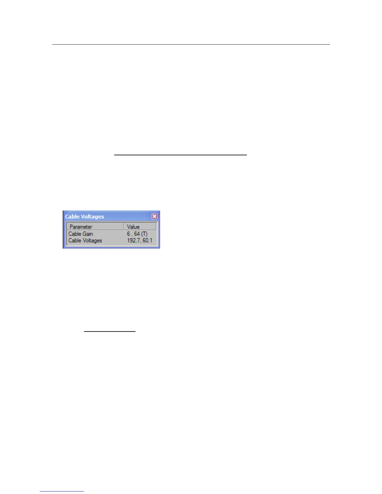
The TTM output DC voltage is set at 200 VDC.
The Cable Voltage at the head is 192.7 VDC
Total DC voltage drop along the 3
rd
wire cable is 7.3 VDC.
The TTM AMP meter located on the front panel indicate a current of 0.3 A. Therefore the
calculated total resistance of the 3
rd
wire cable is:
R =
The maximum allowable closed loop cable resistance is 100 ohms.
5.4.5.3 Test for Water Ingress in the Trawl Cable
When a trawl cable is damaged or there is a poor splice, sea water can get into the cable.
As a result, the cable may act as a battery - producing a small dc voltage across the
conductors of the cable. This is detrimental to the operation of the FS system and all
affected cable should be removed.