Do you have a question about the Simrad FS 70 and is the answer not in the manual?
Introduction to the SIMRAD FS 70 Series trawl monitoring system for fishing trawlers.
Lists the essential components that comprise a typical FS70 Trawl Monitoring System.
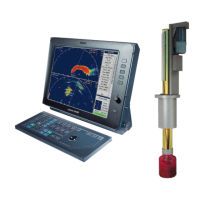
Illustrates common system configurations for 70 kHz and 40 kHz setups.
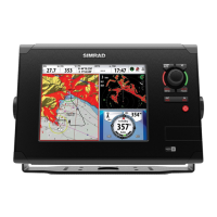
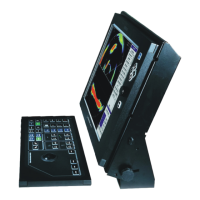
Describes the LCD monitor used with the FS 70 system for displaying sonar data.
Details the PC unit acting as the control unit and its various connectors.
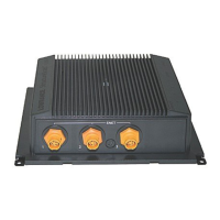
Explains the module that provides supply voltage and telemetry translation for the sonar.
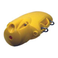
Describes the polyurethane housing designed for the trawl unit in harsh environments.
Information on tools and materials required for splicing the trawl cable.
Details wireless sensors mounted on the cod-end to detect net stretch and catch.
Describes the integration capabilities with Simrad PI System sensors.
How the system outputs NMEA data for depth, temperature, and PI sensors.
Information regarding the trawl cable, winches, and pulley blocks used with the system.
Explains the fundamental operational theory of the Vertical and Sounder Scanning Trawl Monitoring Sonar System.
Covers the basic principles of sound wave propagation and reflection for sonar operation.
How the system measures time to convert sonar pulse reception into distance and bearing.
Explains signal attenuation, TVG, and how data is plotted on the video display.
Introduces and describes some of the key features of the FS 70 System.
Details how the AGC algorithm adjusts gain based on acoustic returns.
Explains how the RCG filter senses noise and adjusts gain to improve image clarity.
Describes setting the response and type for gain algorithms like AGC and RCG.
Details how pulse length can be adjusted to optimize image detail or range.
Explains the Peak Detection method for improving echo detection between samples.
Overview of the typical screen layout and components of the DATSS Sonar Processor.
Lists the minimum and recommended hardware specifications for the system processor.
Provides step-by-step instructions for installing the DATSS software from CD/DVD.
A summary of key operations and system starting procedures.
Instructions on how to launch the DATSS software application.
Details on how to operate the sonar system, including scan modes and bandwidth.
Explains the different scan modes available: Polar, Sector, Net Opening, Sounder, Lock.
Options for selecting bandwidth: Wide, Medium, and Narrow for image quality.
Instructions on how to increase or decrease gain to affect image intensity.
Details the available scan speeds for the sonar head in Polar and Sector modes.
Selecting gain processing types: AGC, RCG, or a combination of both.
Options for selecting low resolution for faster scans or high resolution for better image quality.
How to access and use different sonar operation pages.
Details the scan page used to control scan mode, speed, and area.
Controls transmission parameters from the sonar head.
Used to control the Time Varying Gain (TVG) characteristics for the sonar.
Adjusts trawl sensor display information and settings.
Details the sonar image display, including measurement overlays.
How to use cross-hair markers to measure range and bearing on the sonar image.
Describes the annotation (Pencil) and deletion (Wiper) tools available.
Explains the use of gauge windows for displaying parameter data.
Configuration for importing and exporting NMEA data.
Steps for importing NMEA standard sensor data like GPS.
Guide to defining custom sensors for NMEA data input.
Configuring COM port parameters for optimal sensor data reception.
Verifying sensor data reception through the COM port on the Test page.
Procedures for recording, playing back, and exporting sonar data.
Instructions on how to record sonar data and settings to .smb files.
Steps to playback recorded .smb files using the software.
Configuring the system to export data to a COM port.
How to save sonar images and overlays as BMP files.
Overview of the main modules comprising the DATSS user interface.
Adjusting system parameters directly via the Control Panel interface.
Selecting operational settings for the active sonar via the 'Operation' tab.
Selecting display settings for the active sonar via the 'Display' tab.
Setting up system parameters for the active sonar via the 'Setup' tab.
Setting sonar configurations based on previously saved user settings.
Selecting and setting up the desired sensors for system operation.
Configuration details for PI 40 kHz channel sensors.
Setting up receiver parameters for PI 40 kHz sensors.
Menu for turning PI 40 kHz sensors ON or OFF.
Menu for turning PI 70 kHz sensors ON or OFF.
Accessing parameters for advanced users, typically not needing frequent changes.
Selecting Time Varying Gain (TVG) settings from a dropdown menu.
Adjusting the sonar transducer orientation (Fore or Aft).
Configuring hardware synchronization modes for multiple sonar heads.
Enabling a filter to remove unwanted acoustic interference from the signal.
Selecting color palettes for the display of the sonar image.
Accessing advanced menu options, including the View Menu.
Understanding the status bar colors that indicate different system statuses.
Selecting system modes such as Run, Playback, or accessing Help.
Displaying sensor data with digits and symbols for easy interpretation.
Indicates the status of sensors installed with the deployment pack.
Shows the status of sensor configuration and data reception.
Displays activation status and data validity for catch sensors.
Indicates depth sensor readings and their trends over time.
Displays temperature sensor readings and trends.
Indicates door spread distance and measures door movement.
Measures distance from the headrope to trawl doors or wing ends.
Explains common file extensions used by the system (.EXP, .LOG, .SMB).
Steps to initialize, calibrate, and start the sonar system.
Overview of the essential steps involved in installing the FS 70 Trawl Monitoring System.
Detailed instructions for installing the various units in the wheelhouse.
Guidelines for properly mounting the display and processing units in the wheelhouse.
Details the power requirements and voltage selection for the system components.
Instructions on connecting monitors to the FS70 Processor unit.
Description of the Power/TTM interface unit's front and rear panel features.
Information and steps for connecting the FS 70 Processor unit.
Details the ID, application, and description of all interconnect cables.
Instructions for connecting the required USB security key.
Steps for connecting USB/RS232 converters to the TTM unit.
How to connect a GPS unit to the serial port for NMEA data input.
Connecting an echo sounder to display trawl unit depth on the sounder.
Connecting a heading sensor to the serial port for heading information.
Making the connection between the TTM interface unit and winch/slip-rings.
Steps for assembling the trawl unit, including sealing and housing.
Details the standard FS 70 trawl configurations and their components.
Initial power-up, set-up, and testing procedures using the supplied test cable.
Setting up communication between the FS Processor and the TTM unit.
Procedures for the initial power-up of the entire system.
Configuring trawl unit parameters after initial power-up.
Choosing the correct trawl voltage setting for the underwater trawl unit.
Performing a final system test before completing the trawl unit assembly.
Final steps in assembling the trawl unit, including sealing connectors.
Proper mounting procedures for catch sensors on the cod-end of the net.
Describes the mounting locations for PI Geometry sensors on the trawl.
Recommended receiver settings for PI systems for optimal performance.
Overview of instructions for proper handling, maintenance, and troubleshooting.
Describes the wheelhouse electronics and trawl unit components.
Common causes of failures and the importance of proper handling and maintenance.
Maintenance guidelines for the wheelhouse electronics components.
Handling and maintenance crucial for ensuring trouble-free operation of the trawl unit.
Essential tips for careful handling of the trawl unit to prevent damage.
A schedule for routine maintenance to ensure optimal system performance.
Proper procedures for maintaining connectors to prevent failure and water damage.
Discusses potential damage to the trawl unit from excessive impacts.
Guidance on cleaning and sealing areas where corrosion has occurred.
Instructions for inspecting the transducer and shaft for any signs of damage.
Maintenance information for FA 701 and PI 32 catch sensors.
Importance of winch slip-rings and trawl cable for system operation.
Using available tools to check and monitor system performance for early problem detection.
Lists the tools available for troubleshooting the FS system.
Using a test cable for quick verification of problems related to the trawl cable or slip-rings.
Monitoring voltage and ampere meters to check trawl unit power requirements.
Checking cable compensation gain to monitor the condition of the 3rd wire trawl cable.
Procedures to determine if the trawl cable is faulty and requires troubleshooting.
Using a Mega-Ohmmeter to check the impedance of the trawl cable.
Checking closed loop resistance, voltage, and current at the trawl unit.
Testing the trawl cable for signs of water ingress.
Identifying and resolving telemetry errors that may affect sonar operation.
Saving screen displays in different ways for system analysis.
Page providing pertinent system information for factory troubleshooting assistance.
Saving snapshots of the sonar display screen.
Starting and stopping manual recordings of the display.
Automatic background recording for future analysis of system issues.
Accessing and transferring saved system files to a service provider.
Using system tools and performance records for effective problem diagnosis.
General steps for troubleshooting system problems and identifying causes.
Understanding the sequence of events during system power-up.
Addressing telemetry communication and potential issues during software start-up.
Steps that occur after host software detection and clicking the 'Run' button.
A list of available technical drawings for the FS 70 system.
| Display Type | LCD |
|---|---|
| Power Output | 1 kW |
| Frequency | 20 - 30 kHz |
| Display | Color LCD |
| Operating Temperature | -15°C to 55°C |