FS 70 Installation Instructions
974-24007001/5.0 73
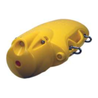
The PI Geometry sensors are mounted behind the headrope at the top of the trawl opening,
or behind the footrope at the bottom depending on the required application.
The two Mini-R responders are normally mounted in dedicated adaptors on the two doors.
They may also be mounted on the trawl wings.
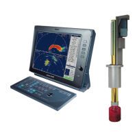
Communication link between the PI sensors and the two Mini-R responders may be done
via the FS 70 head rope unit forward hydrophone located inside the DP housing or via the
PI hydrophone mounted below the ship hull.
Refer to the SIMRAD supplied PI Net Geometry Installation Manual for additional
information.
4.3.9 PI Receiver Basic Configuration Settings
When you put the PI Geometry to use, you must set it up with one unique sensor number
with two measurements. Only one update rate can be chosen, this is common for both
measurements. The channel numbers are defined individually for the two measurements.
Both the update rate and the channel numbers must be chosen according to the sensor’s
configuration. Write down this configuration for future reference.
For default settings, to the SIMRAD supplied PI Net Geometry Installation Manual table in
section about sensor configuration.
If your PI system is fitted with MMI software version 0.50 and DSP software version 1.11
or later, use the following recommended receiver settings:
– Interference filter: On
– Interference filter level: 8
– Sensor filter: Light
– Catch/Bottom sensor filter: Light
– AGC: Off
– Manual gain: 20 dB
– Multipath filter: On
– Water profile: Salt
– Detection threshold (DT): 8 dB
– Maximum shooting speed: 1 knot