EasyManuals Logo

Simrad GO7 User Manual

Simrad GO7
122 pages
To Next Page IconTo Next Page
To Previous Page IconTo Previous Page
Page #94 background imageLoading...
Page #94 background image
For other vessels COG data is included in the message received
from the AIS system.
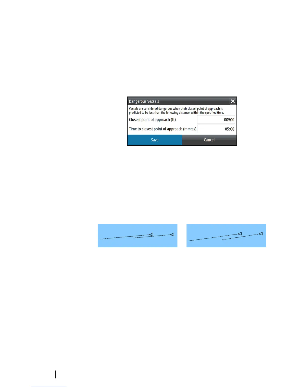
Defining dangerous vessels
You can define an invisible guard zone around your vessel. When a
target comes within this distance, the symbol changes to the
“dangerous” target symbol. An alarm is triggered if activated in the
Alarm settings panel.
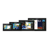
Speed and course indication
The extension line can be used to indicate speed and course for
targets, either as absolute (true) motion in the chart or relative to
your vessel.
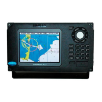
A different line style is used on the extension lines to indicate
motion, as shown below.
AIS vessels shown with Absolute motion
AIS vessels shown with Relative motion
AIS icon orientation
Sets the orientation of the AIS icon, either based on heading or COG
information.
94
AIS | GO7 Operator Manual

Table of Contents

Other manuals for Simrad GO7

Questions and Answers:

Question and Answer IconNeed help?

Do you have a question about the Simrad GO7 and is the answer not in the manual?

Simrad GO7 Specifications

General IconGeneral
Resolution800 x 480 pixels
TouchscreenYes
NetworkingNMEA 2000
BluetoothYes
ChartplotterYes
Display Size7 inch
GPS TypeInternal
Wireless ConnectivityWi-Fi
Chart CompatibilityC-MAP, Navionics
Display TypeTFT LCD
SD Card Slots1
Sonar CompatibilityCHIRP
Radar CompatibilityYes
Operating Temperature-15°C to 55°C
SonarBroadband, CHIRP, DownScan, SideScan (with compatible transducer)

Related product manuals