12 | Installing the display
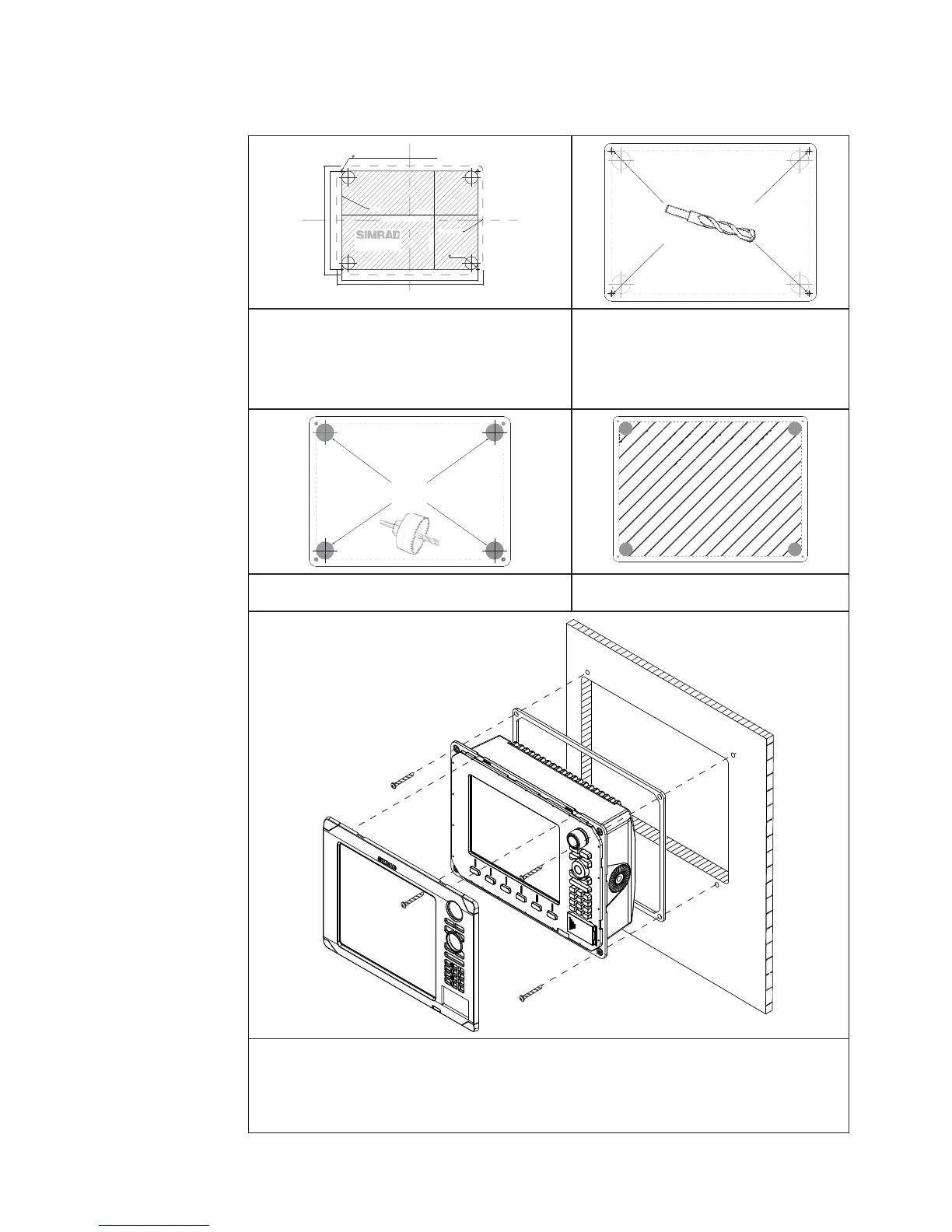
Cut out shaded
area
Panel mount
212 mm (8.34”)
285 mm (11.20)
265 mm (10.40”)
CLEARANCE HOLE TO SUIT M4 MACHINE SCREW
OR DRILL PILOT HOLE TO SUIT SELF TAPPING SCREW
5 mm (0.20”)
192 mm (7.55)
NSE-8
192 mm (7.55”)
265 mm (10.40”)
PRODUCT OUTLINE
25 mm (1.00”)
CUTOUT
Check dimensions before cutting
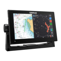
1 Attach the fl ush mounting template to
the selected mounting position using
adhesive tape.
2 Drill pilot holes for the four hole
saw cuts and four self tapping
screws used to secure the
display. If using M4 machine
screws use a 5 mm (0.20 ”) drill
bit.
A
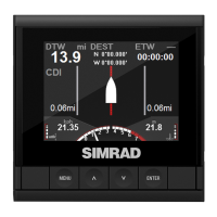
3 Use a 25mm (1 “) hole saw to cut the
four corner radius
4 Cut along the dotted line and
remove the shaded area.
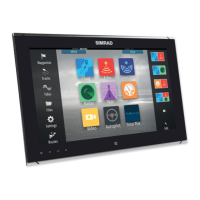
5 Peel backing off the gasket and apply to the surface.
6 Connect all cables to the rear of the unit before placing the unit into the console.
7 Secure the display to the surface
8 To fi nish off the installation fi rmly clip the front bezel in place