62 | Commission the system
20%
10
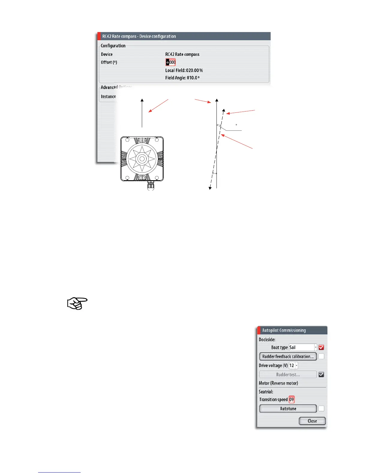
Magnitude of local fi eld
in % of earth’s magnetic
fi eld.
LUBBER LINE
Direction of local fi eld
with respect to lubber
line. It can also be on the
reciprocal.
In certain areas and at high latitudes the local magnetic interference becomes more
signifi cant and heading errors exceeding ±3° may have to be accepted.
Compass mounting offset
After compass calibration, the difference between the compass lubber line and the boat’s
center line should be compensated for.
1 Find the bearing from the boat position to a visible object. Use a chart or a chart
plotter
2 Steer the boat so that the center line of the boat is aligned with the bearing line
pointing towards the object
3 Change the offset parameter so that the bearing to the object and the compass
readout becomes equal. Refer graphic above
Make sure that both the compass heading and the bearing to the object have the same
unit (°M or °T).
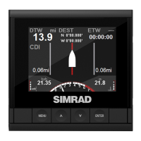
Setting the transition HI/LO speed
This is the speed at which the system automatically
changes from LO to HI steering parameters.
On power boats it is recommended that you set a value
that represents the speed where the hull begins to plane
or the speed where you change from slow to cruising
speed.
On sailboats the transition speed should be set to 3-4
knots to give the best response in a tack.