3
- 29 -
951-180-083-EN
Version 01
EN
3. Overview, functional description
3.3 Information on volume data
In centralized lubrication systems, the nomi-
nal volume is indicated per stroke. This is
calculated from the piston diameter and the
maximum possible stroke of the particular
metering piston, the maximum stroke. The
maximum achievable piston capacity is typi-
cally used as the nominal volume when con-
figuring a progressive metering device,
though the movement of the piston is influ-
enced by various factors such as:
○ Differences in back pressures at the
outlets, for example due to long tubing
lengths or connected roller bearings or
shaft bearings.
○ Stroke frequency (dynamics)
○ Working temperature, viscosity fluctua-
tions due to strong temperature changes
The maximum stroke and thus the piston
capacity/metered quantity can reduce due to
these factors. The minimum piston stroke,
also referred to as the compulsory stroke,
is determined by the position of the control
bores in the metering device and the con-
trol edges on the metering piston. If only
the compulsory stroke is performed, the
metered quantity at the affected outlet is
reduced, which also increasing the effective
number of piston strokes. The theoretically
determined number of piston strokes can
therefore deviate from the actual measured
value. This must be considered when evalu-
ating pulses on metering devices with a
mounted piston detector.
The ratio of piston capacity per metering
device outlet determines the distribution
ratio of the quantity of lubricant supplied
to the metering device. This distribution
ratio is usually constant under all operating
conditions.
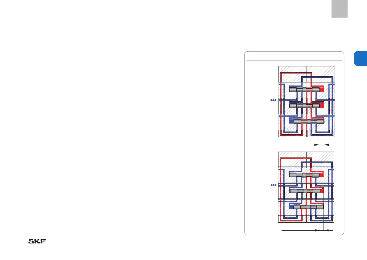
Figure 2 shows the piston positions of a
metering device section at maximum stroke
and at compulsory stroke (minimum stroke).
Fig. 2 Maximum stroke and compulsory stroke
5
5
5
2
5
2
Maximum
stroke for
piston 5 and
piston 2
Compulsory
stroke
for position
of piston 5
Maximum stroke
Compulsory stroke
 Loading...