EN
6. Assembly
- 72 -
951-180-083-EN
Version 01
IMPORTANT
Inlet and outlet fittings - see Chapter 14.3.
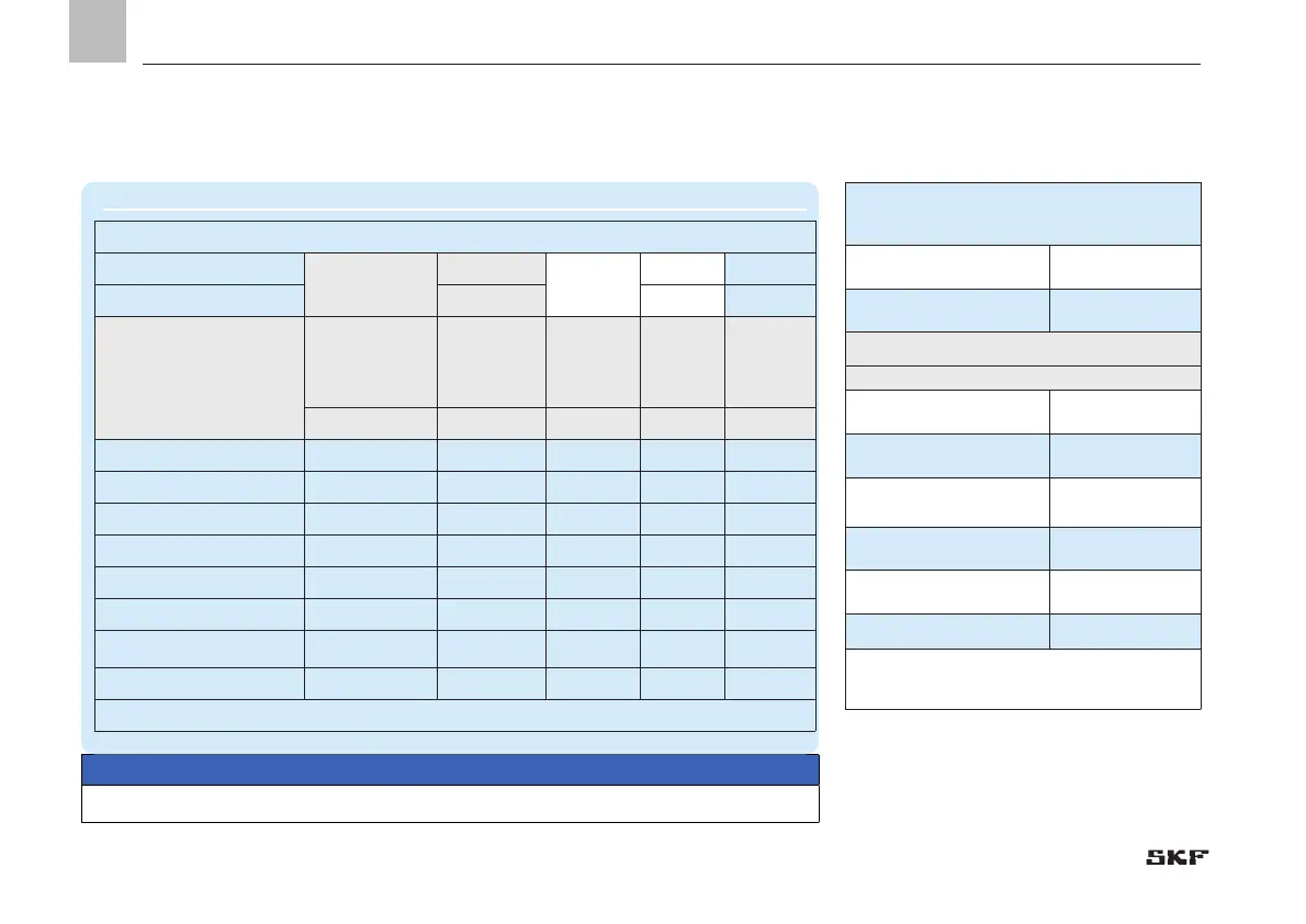
6.5.2 VPB tightening torques
VPB dimensions
Thread connection
VPBM
Inlet:
M10x1
Outlet:
M10×1
VPBG G1/8" G1/8"
Type
Number of
progressive
metering
device sections
Number
of possible
outlets
L Weight
[mm] [kg]
VPBM-3 / VPBG-3
1)
3 6
60 0.75
VPBM-4 / VPBG-4 4 8
75 0.90
VPBM-5 / VPBG-5 5 10
90 1.10
VPBM-6 / VPBG-6 6 12
105 1.30
VPBM-7 / VPBG-7 7 14
120 1.50
VPBM-8 / VPBG-8 8 16
135 1.70
VPBM-9 / VPBG-9 9 18
150 1.90
VPBM-10/VPBG-10 10 20
165 2.1
1) This progressive metering device must be installed with check valves.
The specified torques must be observed during
assembly and repair.
Tie-rod (starter plate)
(M8)
2.4 Nm ± 0.1 Nm
Nut for tie-rod
(M8)
12 Nm ± 1.0 Nm
Inlet and outlet fittings
Type of fitting
Sealing with O-ring 10 Nm ± 1.0 Nm
Sealing with EOlastic ring 10 Nm ± 0.1 Nm
Sealing with copper or alu-
minum ring
15 Nm ± 1.5 Nm
Sealing by sealing edge,
with Loctite 243
15Nm ± 1.5 Nm
Sealing with
Conical nipple
1
)
15Nm ± 1.5 Nm
Plug screw 10Nm+1 Nm
1) Minimum of 9 Nm at drying time of
> 1h sufficient
 Loading...