6
EN
6. Assembly
- 79 -
951-180-083-EN
Version 01
6.7 Electrical connection
DANGER
Excessive switching voltage hazard
If the inductive NAMUR-sensor is
used in a potentially explosive atmo-
sphere (ATEX), a (Namur) isolating
amplifier, connection to certified in-
trinsically safe electrical circuits with
maximum values U = 15 V / I = 50
mA / P = 120 mW must be inserted!
See electrical data for inductive
NAMUR sensor,
VP page 43
VPK page 46
VPB page 49.
Only attachments and monitoring equip-
ment approved by SKF for the metering
devices may be installed.
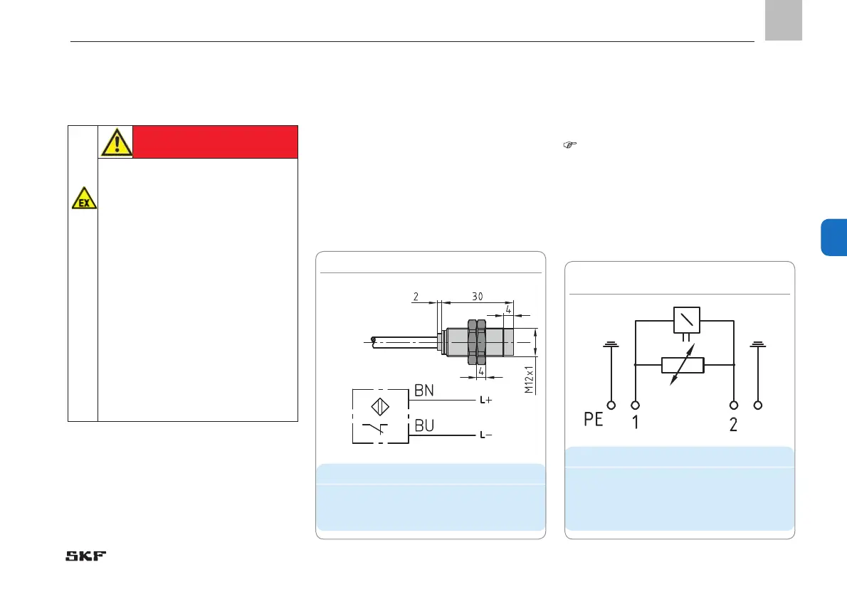
6.7.1 Connecting the inductive
NAMUR sensor
- See Figure 34
• Connect inductive NAMUR sensor ac-
cording to terminal diagram in Figure 34.
6.7.2 Connecting directional solenoid
valves
- See Figure 35
- See electrical data for directional sole-
noid valves, VP page 42; VPK page 45 and
VPB page 48.
• Connect directional solenoid valve ac-
cording to terminal diagram in Figure 35.
Housing
Spare parts
Designation Order number
ATEX Inductive NAMUR
sensor
24-1884-2288
Spare parts
Designation Order number
ATEX 2/2 directional sole-
noid valve
24-1254-2212
ATEX 3/2 directional sole-
noid valve
24-1254-2219
Fig. 34 Connecting inductive NAMUR sensor
Fig. 35 Connecting directional
solenoid valves
 Loading...