- 94 -
951-180-083-EN
Version 01
EN
12. Repairs
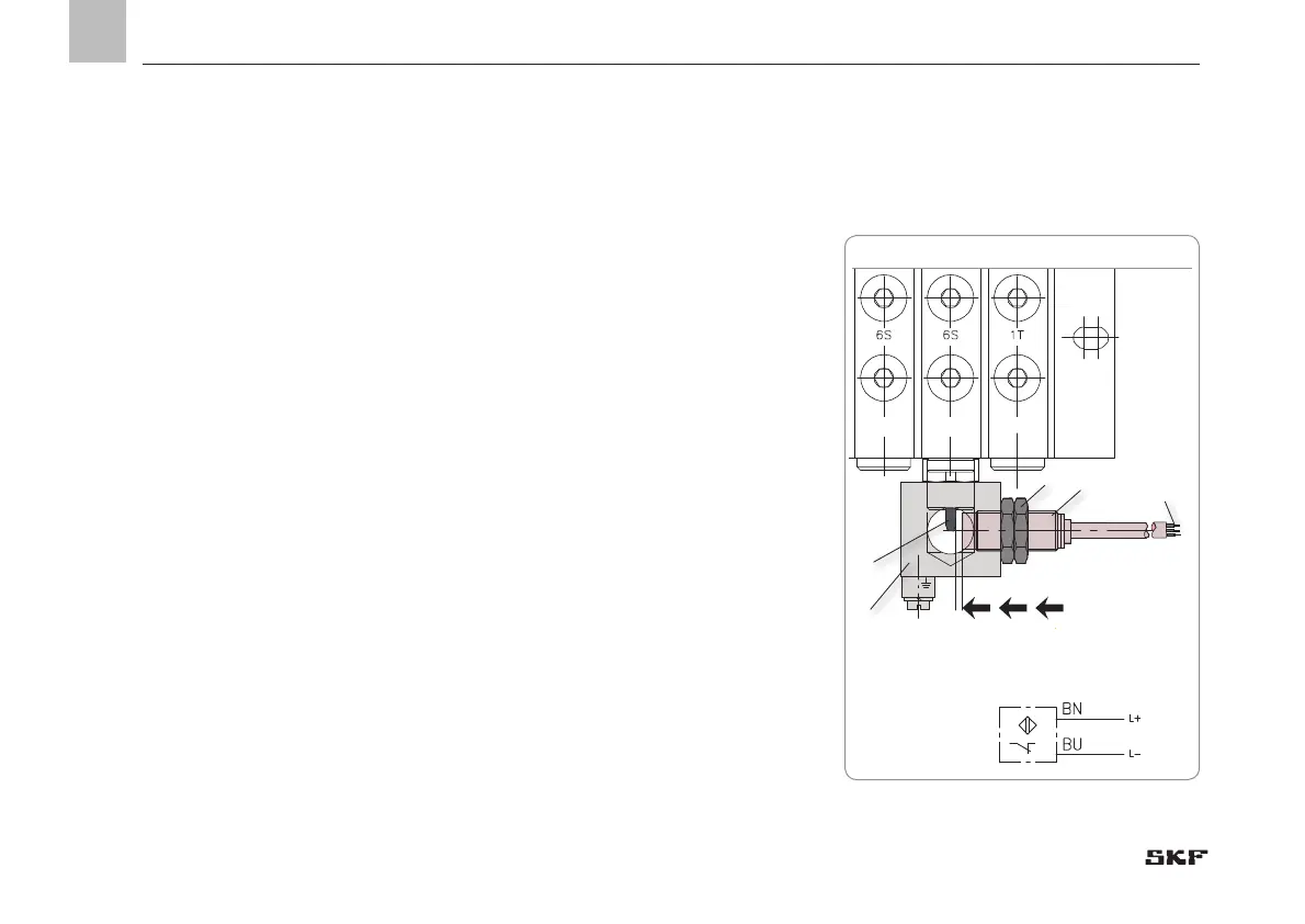
12.2 Replacing inductive NAMUR sensor
-see Figure 43
• Check that the new inductive NAMUR
sensor (2) matches the documentation
and the intended use.
• Disconnect cable end (1) of the defective
NAMUR sensor (2) from the customer's
terminal strip.
• Loosen locknuts (2x 3) from the sensor
holder (4).
• Unscrew defective NAMUR sensor (2)
from the sensor holder (4).
• Apply new NAMUR sensor (2) to the sen-
sor holder (4) and screw in gently.
• Disconnect cable end (1) of the sensor (2)
on the customer's terminal strip.
• Apply pressure to metering device until
the plunger rod (5) has extended.
• Turn on customer's power supply then
screw the NAMUR sensor (2) into the
sensor holder (4) until a sensor pulse is
present on the customer's control unit
(clearance to plunger rod approx. 2 mm)
• Secure NAMUR sensor (2) to the sensor
holder (4) using both locknuts (3).
• Inspections pursuant to the requirements
of the ATEX Directive
4
1
2
2 mm nominal sensing distance
3
5
Fig. 43 Replacing inductive NAMUR sensor
 Loading...