EN
4. Technical data
- 44 -
951-180-083-EN
Version 01
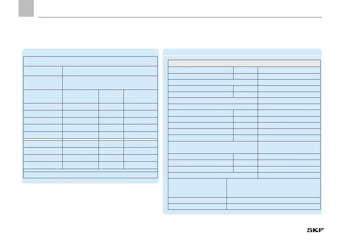
4.2 Volume data for VPK metering device sections
4.2.1 Basic design of VPK progressive metering device
Volume data for VPK metering device sections, Table 6
Max. inlet volumetric flow 500cm
3
/min
Nominal volume Minimum volume
1
)
(at maximum
stroke)
(at compulsory stroke, design value only under
difficult conditions)
Volume per cycle
and outlet
Volume per cycle
and outlet
Number of
outlets
Description of
the sections
[cm
3
] [cm
3
]
0.05
0.04 2 05T
0.10 0.08 2 1T
0.20 0.14
2
2T
0.30 0.18
2
3T
0.10 0.08
1
05S
0.20 0.16
1
1S
0.40 0.28
1
2S
0.60 0.36
1
3S
1) See explanation in Chapter 3.3, Information on volume data.
Progressive metering device VPK, basic design, Table 7
VPK Basic design with terminal for equipotential bonding
Type hydraulically controlled
Mounting position Any
Ambient temperature range -25 to +90 °C
- with cycle indicator -20 to +70 °C
Metering device sections See Table 1
Used outlets, internal connection 3 to 20
Used outlets, external connection 1 to 19
Inlet and outlet threads
VPKM (metric thread) M10x1
VPKG (inch thread) G1/8
Material
Inlet plate, separator plate and end plate Steel, tinned/nitrile-butadi-
ene rubber
Sections (piston plates) Steel, galvanized
Hydraulic system
Operating pressure max.: Oil 200 bar, grease 300 bar
Volume per outlet and cycle See Table 9
Lubricant Mineral oils, greases based on mineral oil,
environmentally friendly and synthetic oils
and greases
Dynamic viscosity > 12 mm
2
/s
Worked penetration ≥ 265 x 0.1 mm (up to NLGI Grade 2)
 Loading...