6
EN
6. Assembly
- 59 -
951-180-083-EN
Version 01
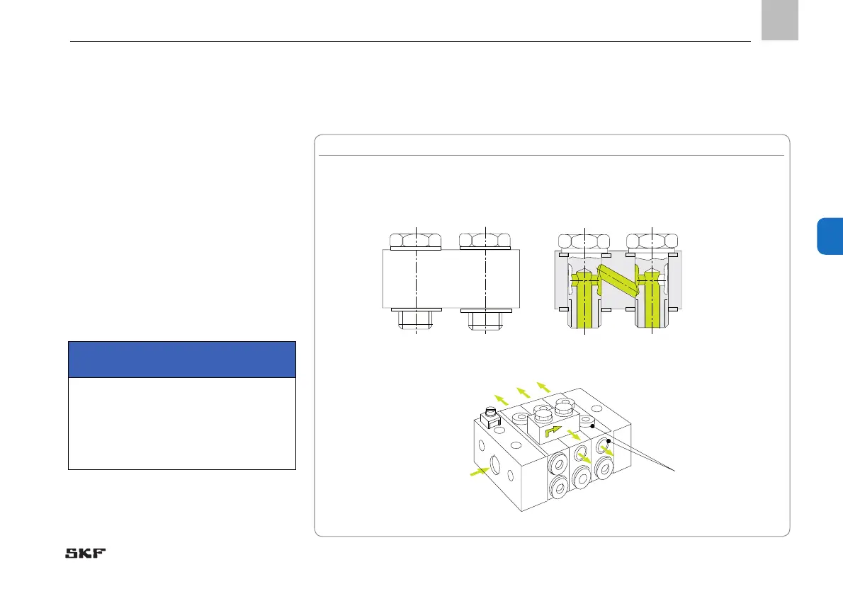
6.3.8 Connecting outlets on the VPM
- See Figure 16
In the VPM series, the metering device sec-
tions have two outlets on each side, one on
the side and one on the top, however only
one may be used. The second outlet must
always be kept closed.
Outlets can only be subsequently consoli-
dated by using a VP-C crossporting bar that
is screwed in the upper alternative outlets.
Any odd number of outlets can be achieved
with the help of single sections without ad-
ditional crossporting bars.
IMPORTANT
Use only one outlet, either outlet top
or side. Crossporting is possible in both
directions.
Alternative outlets.
Use only one outlet!
Crossporting bars, design complete with banjo bolt and sealing rings.
Order No. for VP-C
Fig. 16 Attachment of a VPM crossporting bar.
 Loading...