SMARTRG INC. PROPRIETARY AND CONFIDENTIAL. ALL RIGHTS RESERVED. COPYRIGHT © 2016 8
Connections
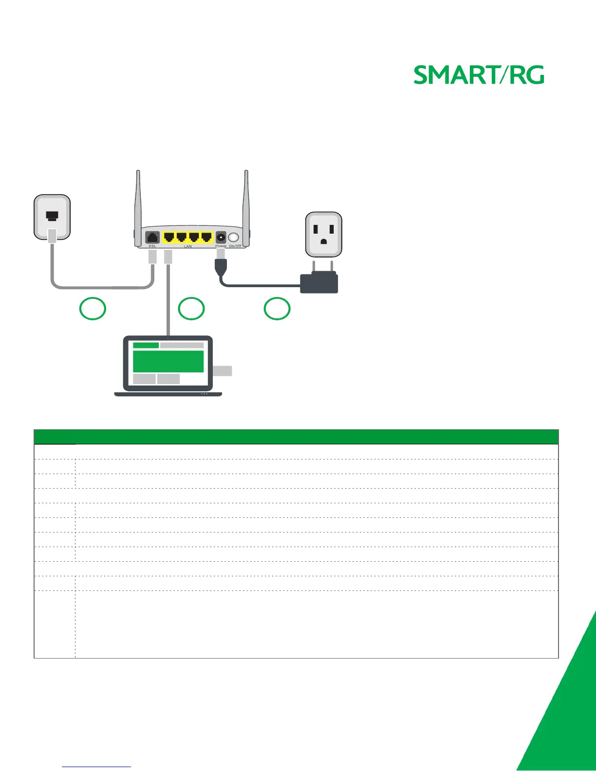
Below is an illustration of the connectors located on the back of the SR506n gateway.
The buttons and ports located on the gateway are described below.
Feature Description
Top
WiFi Button used for enabling or disabling the 5 GHz wireless function.
WPS Button used for enabling or disabling the 2.4 GHz wireless function.
Rear panel
DSL The grey RJ11 port is used to connect your gateway to an Internet provider via a DSL service.
LAN 1 - 4 The yellow RJ45 ports can be used to connect client devices such as computers and printers to your gateway.
Power Use only the power supply included with your gateway. Intended for indoor use only.
On/Off Power switch.
Left side
USB Can transfer data, act as a printer interface, and handle a 3G accessory.
Reset The
Reset
button is a small hole in the gateway's enclosure with the actual button mounted behind the surface. This
style of push-button prevents the gateway from being inadvertently reset during handling. Reset must be actuated
with a paper clip or similar implement.
The Reset button is located on the left side of the unit. Press the button for at least 1 second and release. The factory
default settings are restored.
 Loading...