SMARTRG INC. PROPRIETARY AND CONFIDENTIAL. ALL RIGHTS RESERVED. COPYRIGHT © 2016 88
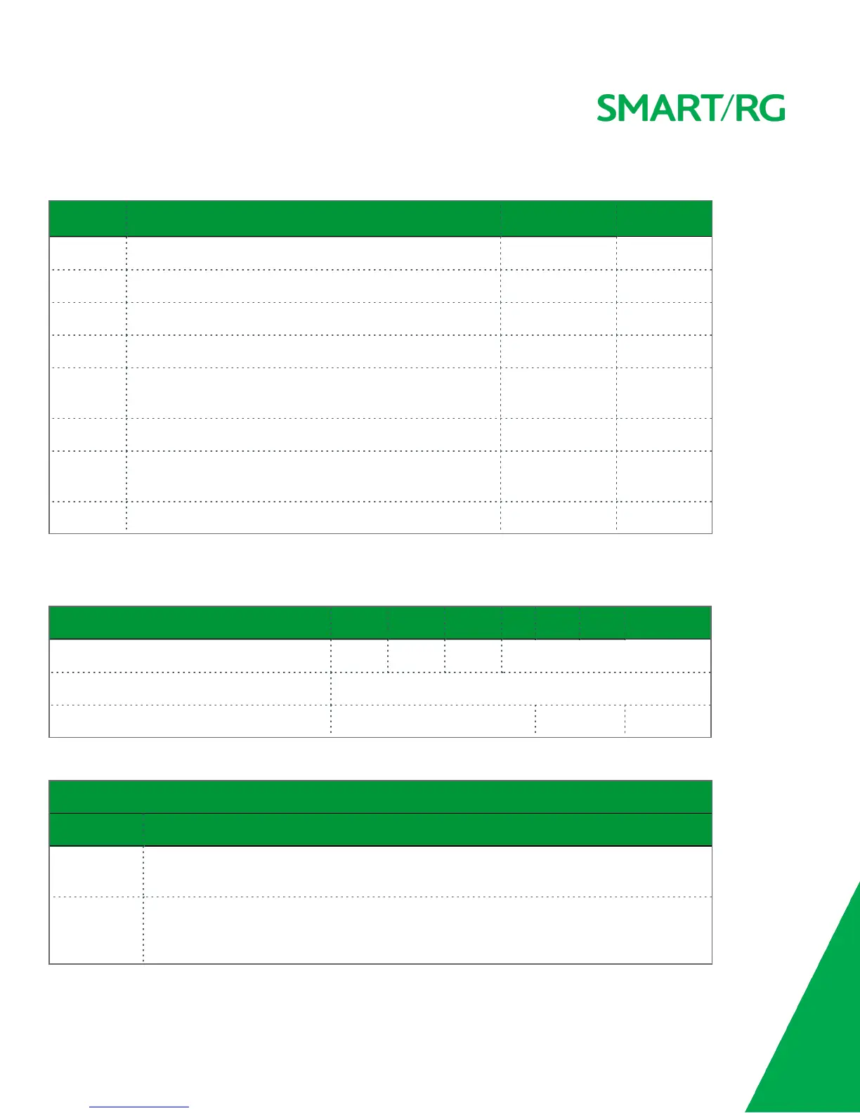
The modulation settings are described in the table below.
Modulation Data Transmission Rate Max Downstream
(Mbps)
Max Upstream
(Mbps)
G.Dmt ITU-T G.992.1 standard.
12 1.3
G.lite ITU-T G.991.2 standard.
4 0.5
T1.413 ANSI T1.413 Issue 2 standard.
8 1.0
ADSL2 ITU-T G.992.3 standard.
12 1.0
AnnexL Annex L of ITU-T G.992.3 standard which supports longer loops
but with reduced transmission rates.
ADSL2+ ITU-T G.992.5 standard.
28 1.0
AnnexM Annex L of ITU-T G.992.5 standard which supports extended
upstream bandwidth.
24 3
VDSL2 ITU-T G.993.2 standard.
100 60
The following table explains the maximum transaction power for each profile supported for SRG gateways.
Parameter 8a 8b 8c 8d 12a 12b 17a
Max DS Tx Power (dBm) +17.5 +20.5 +11.5 +14.5
Max US Tx Power (dBm) +14.5
Min bidirectional net data rate 50Mbps 68Mbps 100Mbps
Other Settings
Field Name Description
Inner
Pair/Outer Pair
The RJ11 connector has four contacts. The center pair of pins is DSL1. The outer pins are the con-
tacts for DSL2. Select which pair should be used.
Capability
l Bitswap Enable: Enables adaptive handshaking functionality.
l SRA Enable: Enables Seamless Rate Adaptation.
l PhyR Enable: Enables Physical Layer Retransmission.
 Loading...