- 18 -
No.EX※※-OMW0011-B
3.2.1. Power/Bus connection
The SI Unit has two Power connectors (XD1/XD2) and two PROFINET communication
connectors (XF1/XF2). If only one connector is used, cover the unused connector with a seal cap so
that the protection rating of IP65 is maintained.
The supply for the logic/sensors "US1" and the supply for the valves/loads "US2" provide the
connected modules and the valve coils via the SI Unit.
The two supplies are isolated electrically and can be switched independently.
Caution
・ Seal caps must be fitted to all unused bus & power connector ports to ensure an IP65 rating.
・ Seal caps must be fitted to all unused bus connector ports to prevent eye exposure to the light
beam from the SCRJ connectors for the EX245-SPN1A
・ Power and bus lines must be installed correctly.
・ To prevent manifold components of the SI Unit from being damaged the supply lines for the
electronics and for the load voltage must be protected externally with a fuse.
・ Maximum loop through current between power connectors on each SI Unit must not be
exceeded.
・ The EX245-SPN1A makes use of a CLASS 1 LASER product. Do not stare into beam visible at
XF1/XF2.
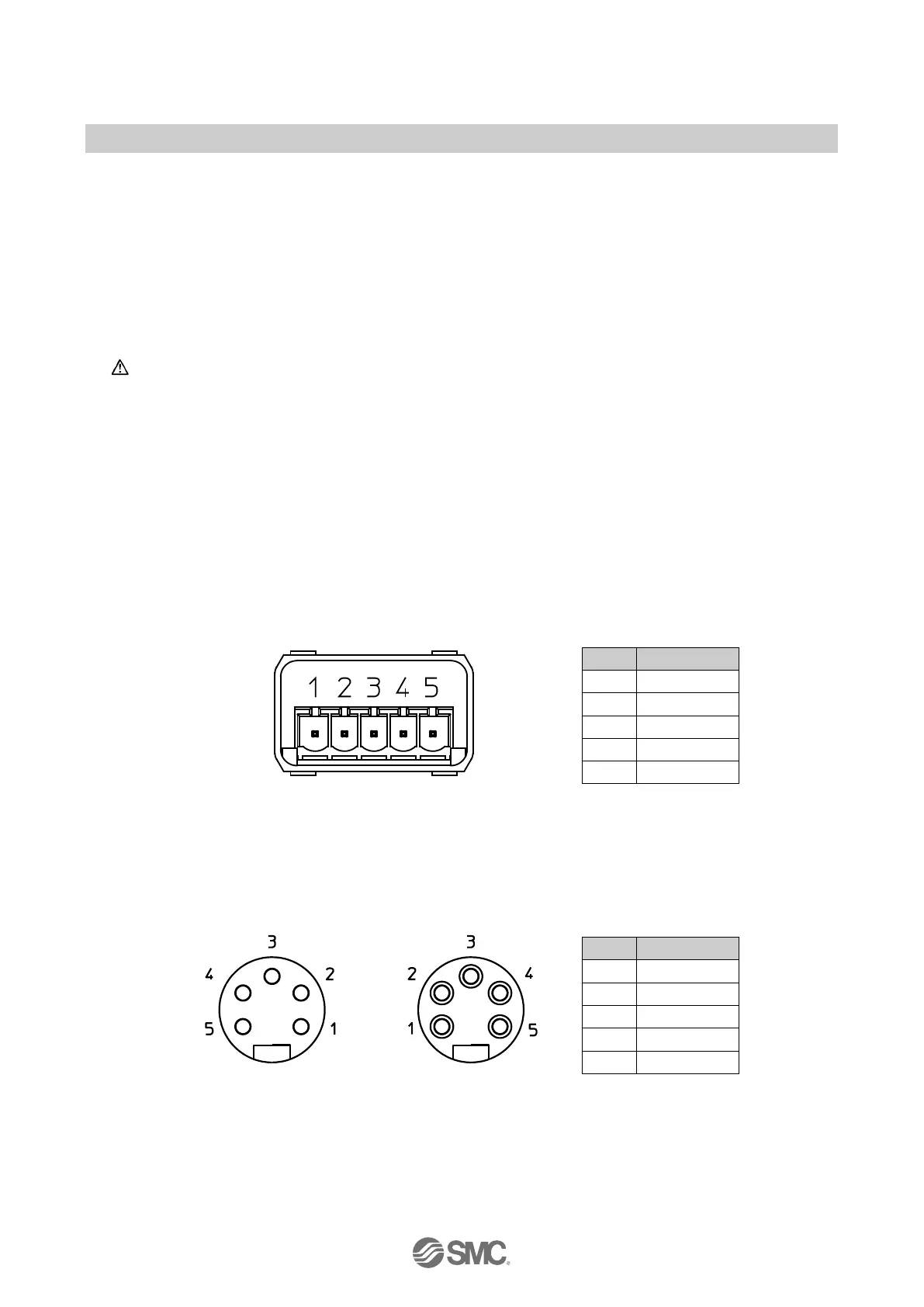
Power connectors
24 V (US1)
0 V (US2)
connector (XD1/XD2)
Fig. 3-6 Pin allocation of Push Pull connector (24 Volt) for EX245-SPN1A/SPN2A
View of 7/8 inch 5 pins
plug connector (XD1)
View of 7/8 inch 5 pins
socket connector (XD2)
Fig. 3-7 Pin allocation of 7/8 inch 5 pins connector for EX245-SPN3A
 Loading...