EasyManuals Logo

SMC Networks EX245-EA2 Series User Manual

Default Icon
85 pages
To Next Page IconTo Next Page
To Previous Page IconTo Previous Page
Page #19 background imageLoading...
Page #19 background image
- 19 -
No.EX※※-OMW0011-B
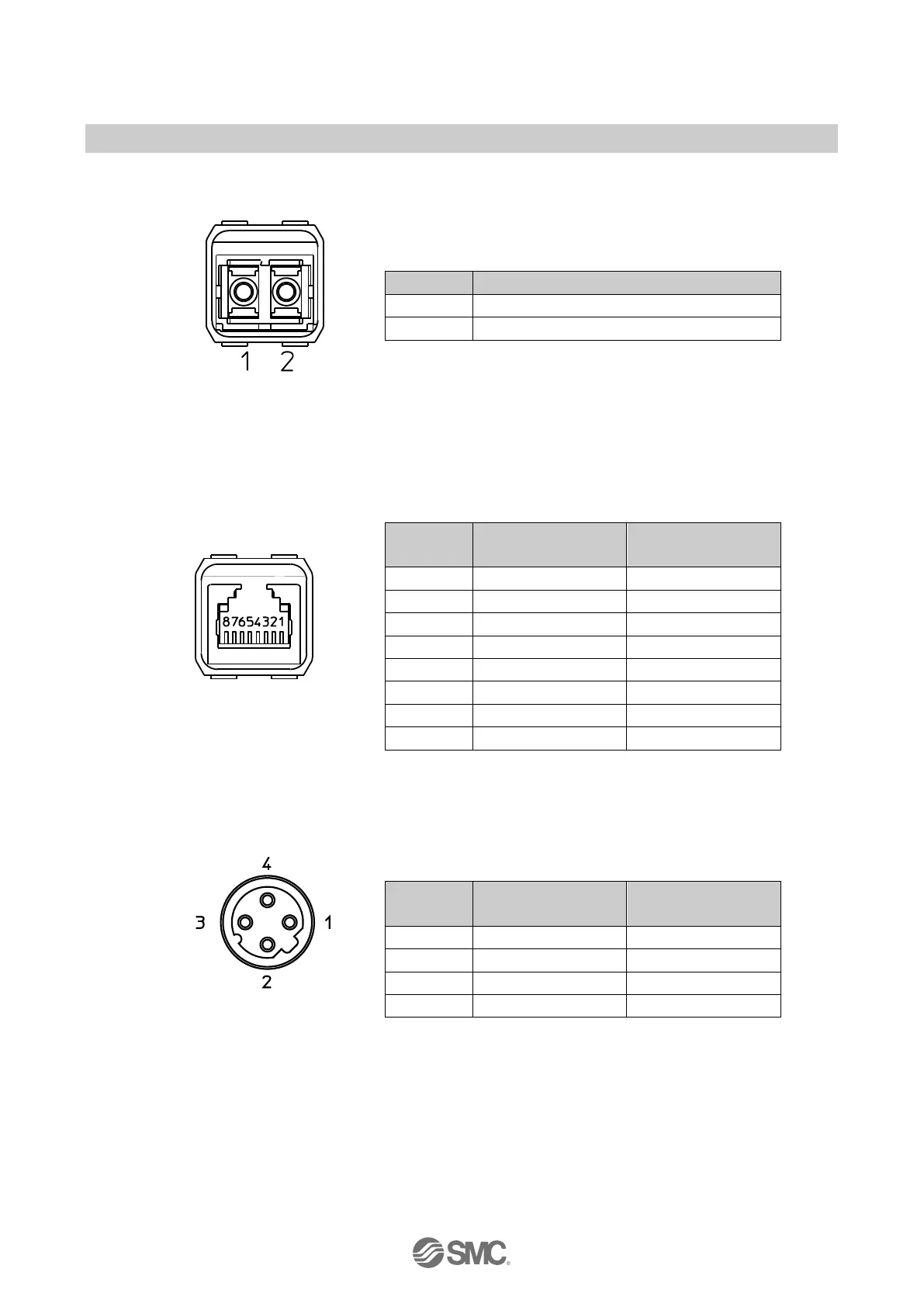
PROFINET communication connectors
Pin
Port1/Port2
1
TX Transmit Data
2
RX Receive Data
View of Push Pull
connector (XF1/XF2)
Fig. 3-8 Pin allocation of Push Pull connector (SCRJ) for EX245-SPN1A
Pin
Port1 (XF1)
Port type: MDI
Port2 (XF2)
Port type: MDI-X
1
TD+ Transmit data+
RD+ Receive data+
2
TD- Transmit data-
RD- Receive data-
3
RD+ Receive data+
TD+ Transmit data+
4
-
-
5
-
-
6
RD- Receive data-
TD- Transmit data-
View of Push Pull
connector (XF1/XF2)
7 - -
8
-
-
Fig. 3-9 Pin allocation of Push Pull connector (RJ45) for EX245-SPN2A
Pin
Port1 (XF1)
Port type: MDI
Port2 (XF2)
Port type: MDI-X
1
TD+ Transmit data+
RD+ Receive data+
2
RD+ Receive data+
TD+ Transmit data+
3
TD- Transmit data-
RD- Receive data-
4
RD- Receive data-
TD- Transmit data-
View of M12 4 pins socket
D-coded connector (XF1/XF2)
Fig. 3-10 Pin allocation of M12 4 pins socket D-coded connector for EX245-SPN3A

Questions and Answers:

Question and Answer IconNeed help?

Do you have a question about the SMC Networks EX245-EA2 Series and is the answer not in the manual?

SMC Networks EX245-EA2 Series Specifications

General IconGeneral
BrandSMC Networks
ModelEX245-EA2 Series
CategoryI/O Systems
LanguageEnglish

Related product manuals