- 25 -
No.EX※※-OMW0011-B
4.1.5. Configuration steps
Enter the modules in your configuration program corresponding to the actual module layout and a
"Diagnostics type" module if required (
Refer to Section 5.1). If the configuration does not match the
actual layout, the connection to the IO Controller will not be established.
Configuration steps:
・ When using the EX245-SPN1A, choose the Head module "EX245-SPN FX" on the
configuration software. When using the EX245-SPN2A/EX245-SPN3A, choose the Head
module "EX245-SPN Cu".
・ Enter the "Diagnostics type 1/2" modules in Diagnostics slot if required.
・ Enter the "16/32 Valves" module in Valves slot if use valves.
・ Enter the modules "EX245-DX1", "EX245-DY1", "EX245-LA1" and "EX245-LB1" in each
module slot if modules are connected (max. 8 modules).
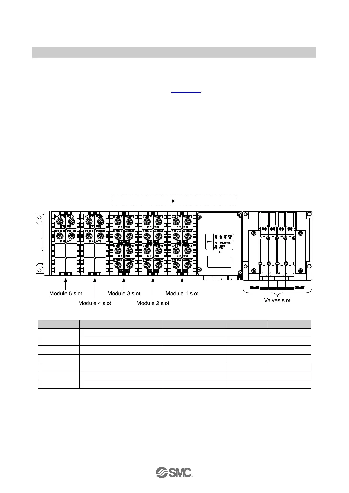
Example of a configuration
Valves 4 x Double solenoid Valves 16 Valves - 2
Module 3 EX245-DX1 EX245-DX1 2 -
Fig. 4-1 Example of assignment of modules
 Loading...