HRX-OM-M090
Chapter 7 Control, Inspection and Cleaning
7.4 Stop for a Long Time HRS Series
7-8
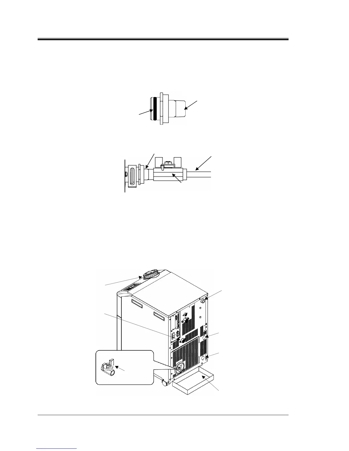
Fitting for the drain port (Accessory)
The thermo-chiller includes the fitting for the drain port shown in Fig. 7-7 .
Discharging of the drain will be easier if customer prepares a valve.
The valve has to be connected to the drain port fitting.
If the valve is connected far away from the drain port fitting, it cause an air trap.
Fig. 7-7 Fitting for the drain port (Accessories)
Fig. 7-8 Example of using fitting for the drain port
Option T [High head pump]
The ball valve is the drain port. Open the ball valve to discharge the circulating fluid in
the same way as procedure 1 to 9.Close the ball valve after discharging the
circulating fluid.
Fig. 7-9 Drain the circulating fluid and facility water from the product for option T [High head pump]
O-ring
Rc3/8
Example)
Drain piping
connected to the
customer’s
equipment
Valve
Fitting for the drain port
Container
Tank lid
Facility water outlet
(For water-cooled type)
Facility water inlet
(For water-cooled type)
Circulating
fluid outlet
Circulating fluid
return port
Ball valve
 Loading...


