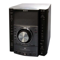
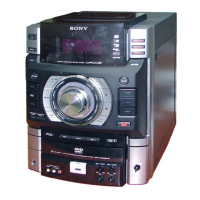
HCD-GT3D
10
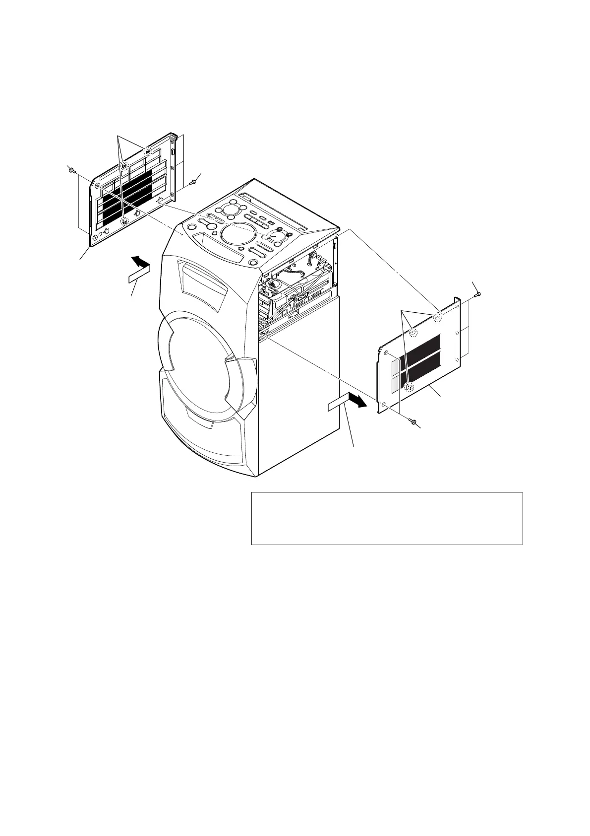
Note: Follow the disassembly procedure in the numerical order given.
2-2. SIDE (L) PANEL, SIDE (R) PANEL
1 two screws
(TAPPING (HEX)
(Type A) or TAPPING
(Type B))
2 three screws (+BVTP 3 × 8)
3 three claws
3 three claws
2 three screws (+BVTP 3 × 8)
1 two screws (TAPPING (HEX)
(Type A) or TAPPING (Type B))
4 Remove the panel, side (L)
in the direction of the arrow.
5 panel, side (L)
4 Remove the panel, side (R)
in the direction of the arrow.
5 panel, side (R)
Ver. 1.2
Note 1: The screw type which screw between “PANEL, SIDE and PANEL,
TOP” and “PANEL, SIDE and CHASSIS” for this unit have been
changed in the midway of production. About the screw type dis-
crimination, refer to “SCREW TYPE DISCRIMINATION BEFORE
DISASSEMBLE THE PANEL, SIDE” on servicing notes (page 6).