ICP-X7000
1-17 (E)
1-4. Installing the Main Panel
n
At least three persons are required to install the main panel
to the adjustment console.
Perform the following procedure to install the main panel.
Prepare the following screws and washers.
For 4-row type (4ME or 3ME AUX BUS integrated type)
. Screw (B4 x 6): 8 pcs
For 3-row type (3ME AUX BUS separate type or 2ME
AUX BUS integrated type)
. Screw (B4 x 6): 6 pcs
For dual-row type (2ME AUX BUS separate type or 1ME
AUX BUS integrated type)
. Screw (B4 x 6): 4 pcs
For single-row type (1ME AUX BUS separate type or
1ME)
. Screw (B5 x 8): 4 pcs
. M5 washer (Sony part number: 7-688-005-11): 4 pcs
For ME separate types (2ME to 4ME separate types or
1ME to 3ME AUX BUS separate types)
. Screw (B5 x 8): 4 pcs (per column)
. M5 washer (Sony part number: 7-688-005-11): 4 pcs (per
column)
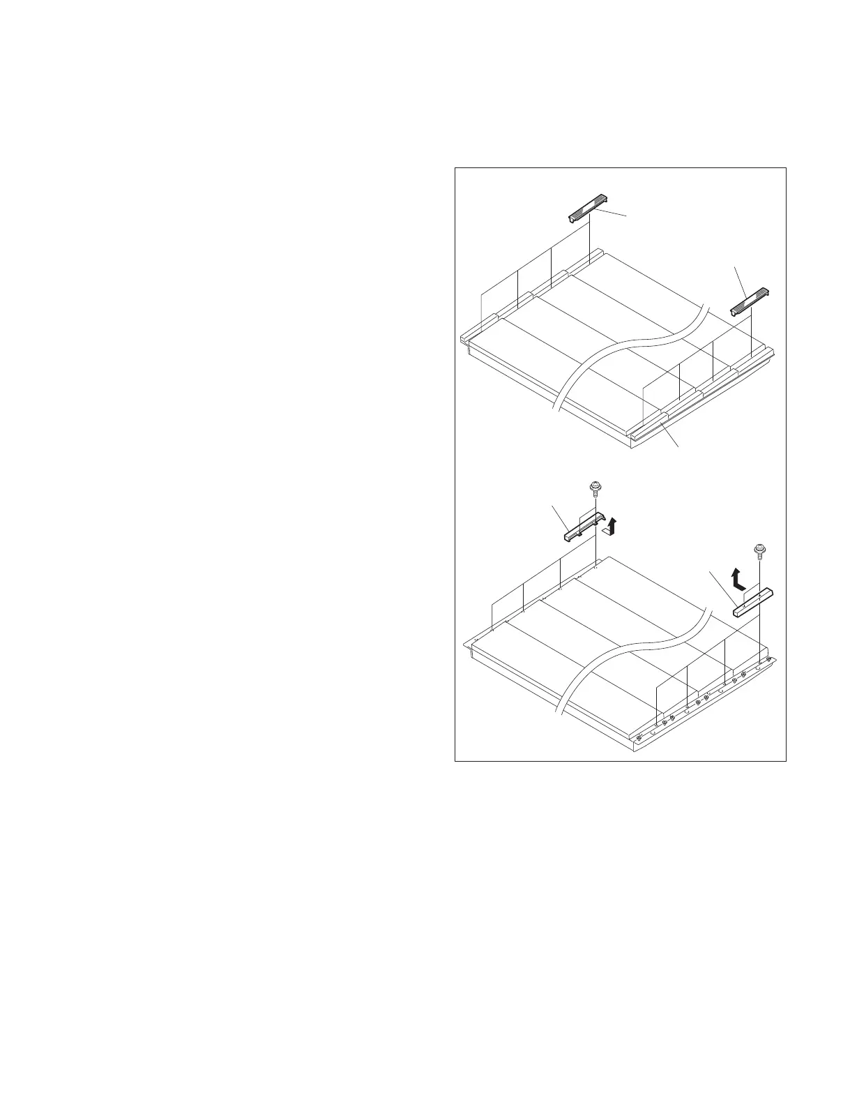
1. Remove the right and left module covers.
2. Remove the screws and detach the caps (L) and caps (R)
in the direction of arrows.
Module covers
Cap
Module covers
PSW3 ) 6
PSW3 ) 6
Caps (R)
Caps (L)

 Loading...


