ICP-X7000
2-6 (E)
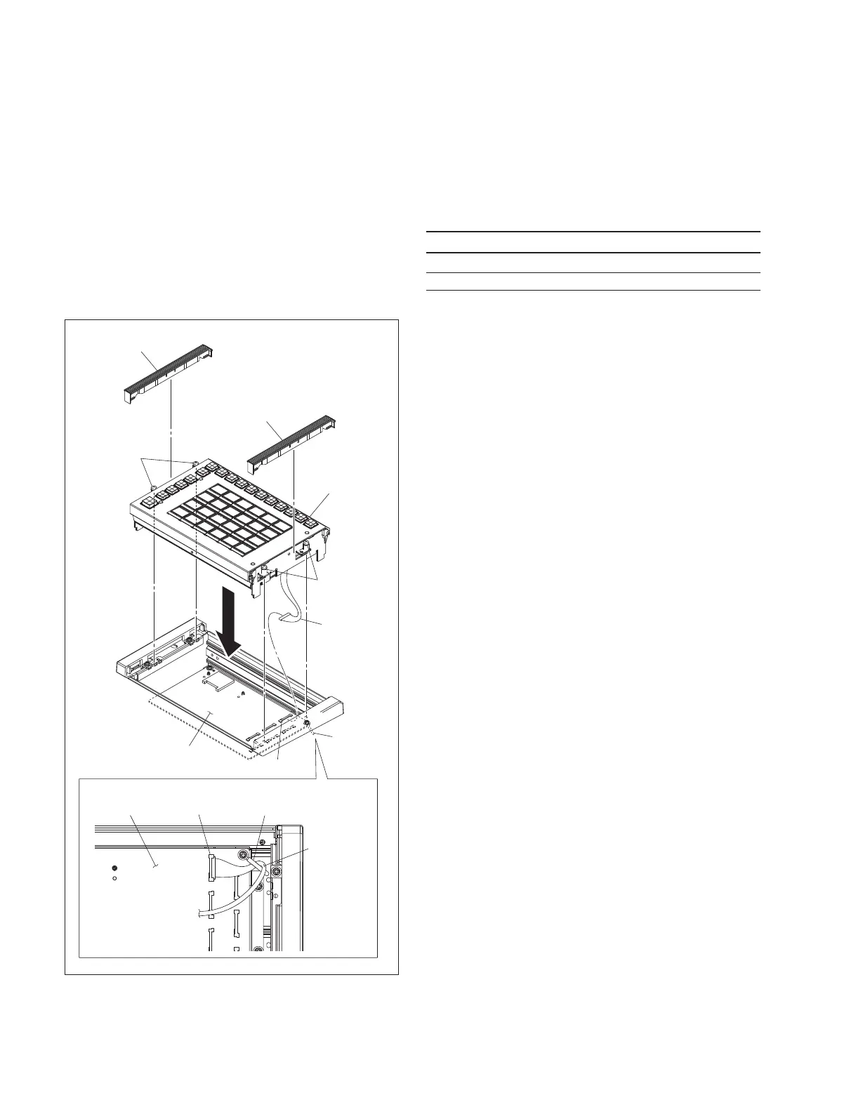
5. Connect the fine-wire coaxial cable to the connector
(CN1100) on the PIF-53 board, and clamp the cable
with a cable clamp.
6. Connect the fine-wire coaxial cable to the operation
module.
7. Fit the operation module and tighten the four screws
(with stopper) on both sides to secure the operation
module.
8. Attach the module covers. (When installing the MKS-
X7031TB, refer to the “Installing the trackball” de-
scribed above.)
2-2. Installing the Connector Board
(MKS-X7700)
The following options are available for the MKS-X7700.
Optional board list
Option name Board name
MKS-X7701 Tally/GPI Output Board CN0-42 board
MKS-X7702 Serial Interface Board CNB-32 board
n
Be sure to turn off the POWER switch before starting
installation work.
If installation work is started with the POWER switch left
on, it may cause electrical shock or damage to printed
circuit boards.
t
SLOT1 to SLOT6 of the unit are optional slots, and SLOT7
and SLOT8 are standard slots.
n
Be sure to install an optional board or a blank panel in each
slot on the rear panel.
CN1100
CN1100
Cable
Clamp
Cable
Clamp
Module cover
Module cover
Operation module
Screws
(with stopper)
Screws
(with stopper)
Fine-wire
coaxial cable
Fine-wire
coaxial cable
PIF-53 board
PIF-53 board

 Loading...


