ICP-X7000
1-54 (E)
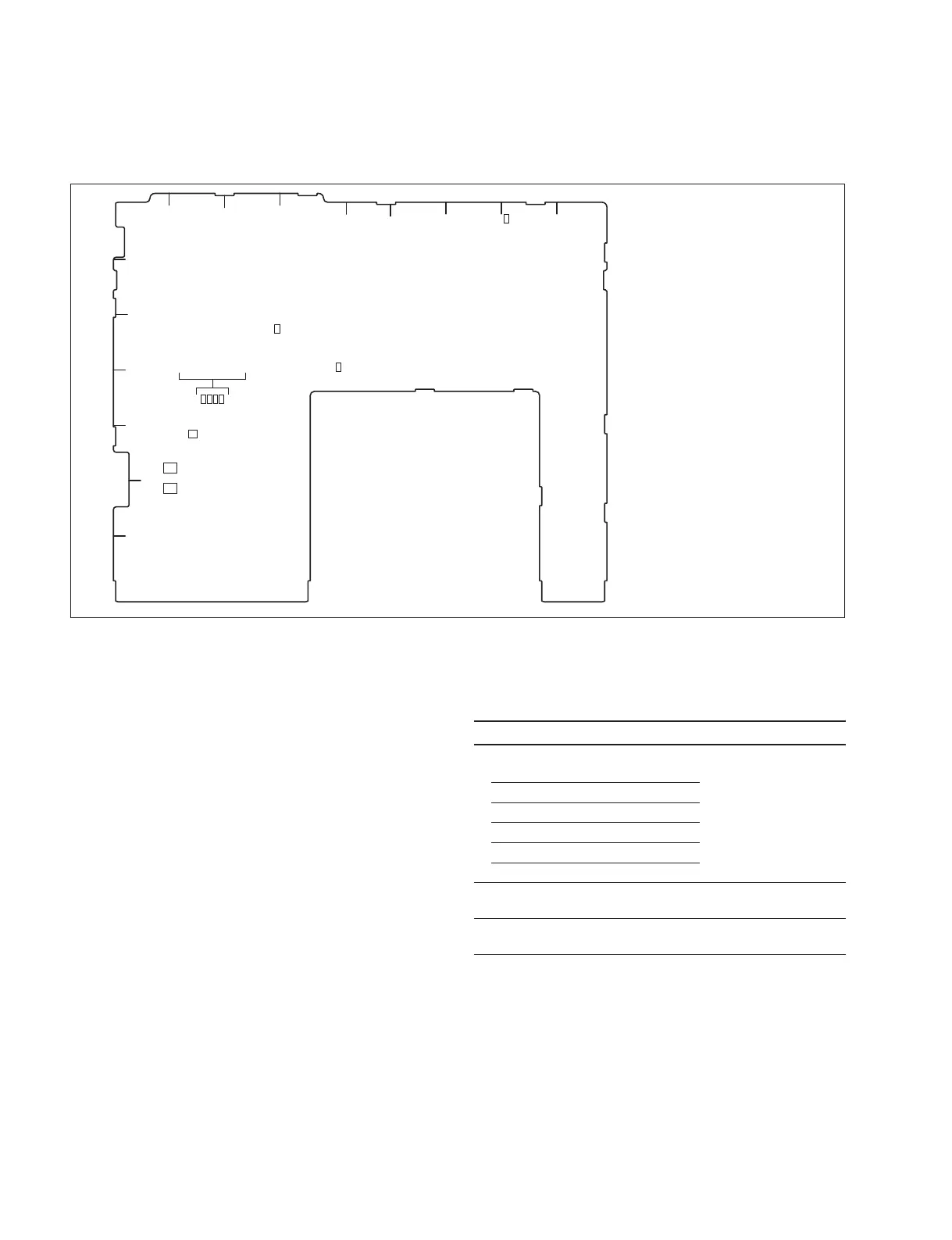
1-14-3. MKS-X7011
CA-91 board (A side)
<LED>
D1101 (D-4): LINK
This LED is lit when the Ethernet links.
D1102 (D-4): ACT
This LED is flashed while the Ethernet is in communication.
D1409 (H-1): 5 V
AUX power supply status indication.
Lit when the +5 V-AUX is supplied correctly.
D1901 to D1904 (B4): Board Status
These LEDs display a startup state of the CA-91 board.
* All of LEDs D1901 to 1904 are lit during normal operation.
CA-91 board (Side A)
S1803
D1101
D1102
D1409
D1901
D1902
D1903
D1904
S1801
S1802
S1901
A
BC
D
EF G
H
J
1
2
3
4
5
6
7
<Switch>
S1801 (A-5): SETTING1
This switch is used to set the configuration when CA-91
board is boot.
Function Factory setting
S1801-1 (Bit1), -2 (Bit2): OFF (-1, -2) both
Boot Device setting
S1801-1 S1801-2
OFF OFF SPI ROM boot
ON OFF SD Card boot
OFF ON Reserved
ON ON Reserved
S1801-3 (Bit3): Used for design OFF (Do not change
this setting.)
S1801-4 (Bit4): Used for design OFF (Do not change
this setting.)
S1802 (A-6): SETTING2
This switch is used for manufacturing at the factory.
Factory setting: All OFF
Do not change this factory setting.
S1803 (B-5): RECONF
This switch is used to forcibly reboot the CA-91 board.
S1901 (C-3): RESET
This switch is used to reset the CPU hardware of CA-91
board.

 Loading...


