ICP-X7000
1-44 (E)
LE-402 board
<LED>
D1: POWER
Power supply unit status indication.
This LED is lit green while +12 V is normally output and
the fans in the power supply unit are normally rotating.
This LED lights red when +12 V becomes abnormal or any
fan in the power supply unit malfunctions.
D2: BEACON
Not used.
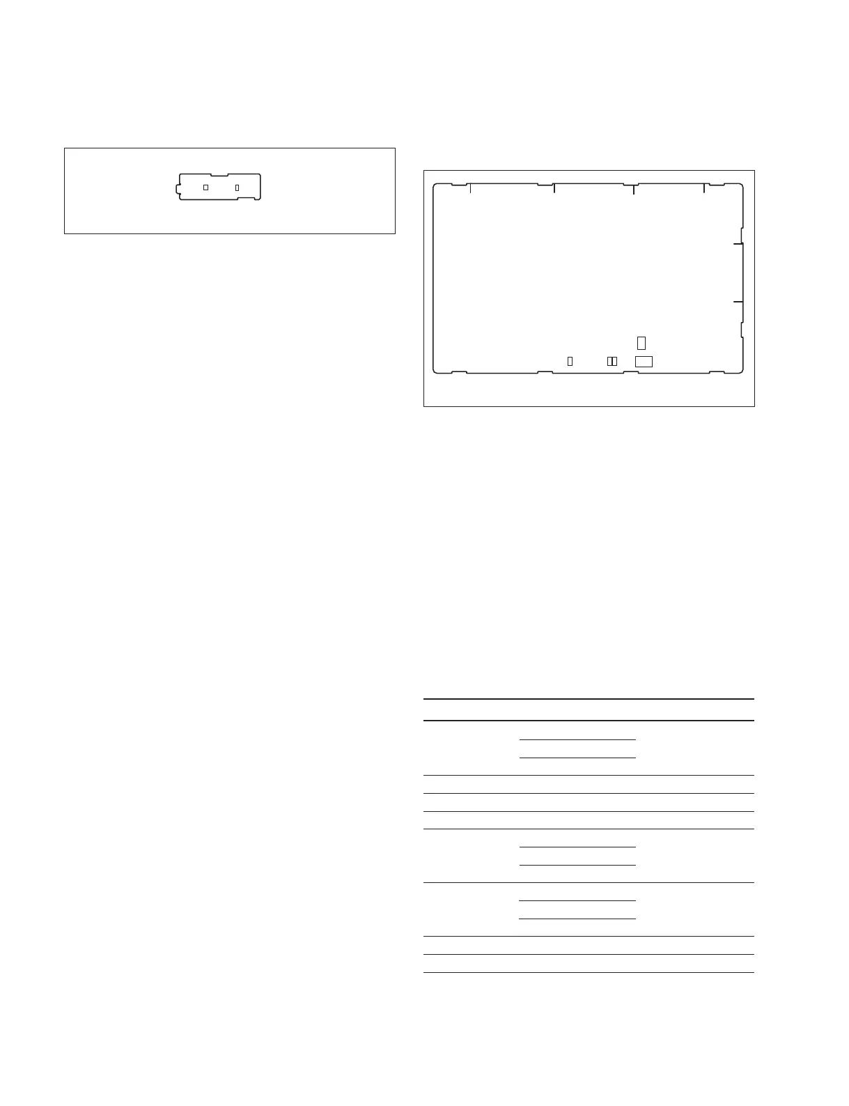
LE-402 board (Side B)
D1
D2
1-14-2. ICP-X7000/MKS-X7075
PIF-53 board
<LED>
D800 (C-3): FPGA Config
This LED lights when configuration of the FPGA is com-
pleted, and it flashes when CPU is boot.
D1200 (C-3): LINL
This LED lights when the Ethernet links.
D1201 (C-3): ACT
This LED is flashed while the Ethernet is in communica-
tion.
<Switch>
S400 (B-3): MODE setting
Function Factory default setting
S400-1 (Bit1) Boot Device OFF
ON: SD Card
OFF: NOR Flash
S400-2 (Bit2) Reserved OFF
S400-3 (Bit3) Reserved OFF
S400-4 (Bit4) Reserved OFF
S400-5 (Bit5) Boot Mode OFF
ON: NBL
OFF: CE-Linux
S400-6 (Bit6) Boot Mode for CE-Linux OFF
ON: Recovery
OFF: Normal
S400-7 (Bit7) Reserved OFF
S400-8 (Bit8) Reserved OFF
S403 (B-3): Reset
This switch is used to reset PIF-53/MPU-163 board hard-
ware.
D800
D1200
D1201
S400
S403
A
BCD
E
1
2
3
PIF-53 board (Side B)

 Loading...


