ICP-X7000
1-31 (E)
1-13. Input/Output Signals of Connectors
Input and output signals of the connectors on the rear panel
are as follows.
1-13-1. MKS-X2700
REMOTE 1 to 6
RS-422A (D-sub 9-pin, Female)
<CONTROLLER>to External Device
SERIAL TALLY1, 2
RS-422A (D-sub 9-pin, Female)
<CONTROLLER>to Tally Interface Unit
Pin No. Signal Name Function
1 FG Frame ground
2 RX_ Received data (_)
3 TX+ Transmitted data (+)
4 GND Common ground
5 _ No Connection
6 GND Common ground
7 RX+ Received data (+)
8 TX_ Transmitted data (_)
9 FG Frame ground
TALLY/GPI OUT 1-18, TALLY/GPI OUT 19-36
(D-sub 37pin, Female)
Relay contacts 30 V 0.1 A
Pin
No.
Signal Name Function
TALLY/GPI
OUT 1-18
TALLY/GPI
OUT 19-36
1 OUT_1A OUT_19A General-purpose relay
output(A)
*1
2 OUT_2A OUT_20A
3 OUT_3A OUT_21A
4 OUT_4A OUT_22A
5 OUT_5A OUT_23A
6 OUT_6A OUT_24A
7 OUT_7A OUT_25A
8 OUT_8A OUT_26A
Pin
No.
Signal Name Function
TALLY/GPI
OUT 1-18
TALLY/GPI
OUT 19-36
9 OUT_9A OUT_27A General-purpose relay
output(A)
*1
10 OUT_10A OUT_28A
11 OUT_11A OUT_29A
12 OUT_12A OUT_30A
13 OUT_13A OUT_31A
14 OUT_14A OUT_32A
15 OUT_15A OUT_33A
16 OUT_16A OUT_34A
17 OUT_17A OUT_35A
18 OUT_18A OUT_36A
19 GND GND GND
20 OUT_1B OUT_19B General-purpose relay
output(B)
*1
21 OUT_2B OUT_20B
22 OUT_3B OUT_21B
23 OUT_4B OUT_22B
24 OUT_5B OUT_23B
25 OUT_6B OUT_24B
26 OUT_7B OUT_25B
27 OUT_8B OUT_26B
28 OUT_9B OUT_27B
29 OUT_10B OUT_28B
30 OUT_11B OUT_29B
31 OUT_12B OUT_30B
32 OUT_13B OUT_31B
33 OUT_14B OUT_32B
34 OUT_15B OUT_33B
35 OUT_16B OUT_34B
36 OUT_17B OUT_35B
37 OUT_18B OUT_36B
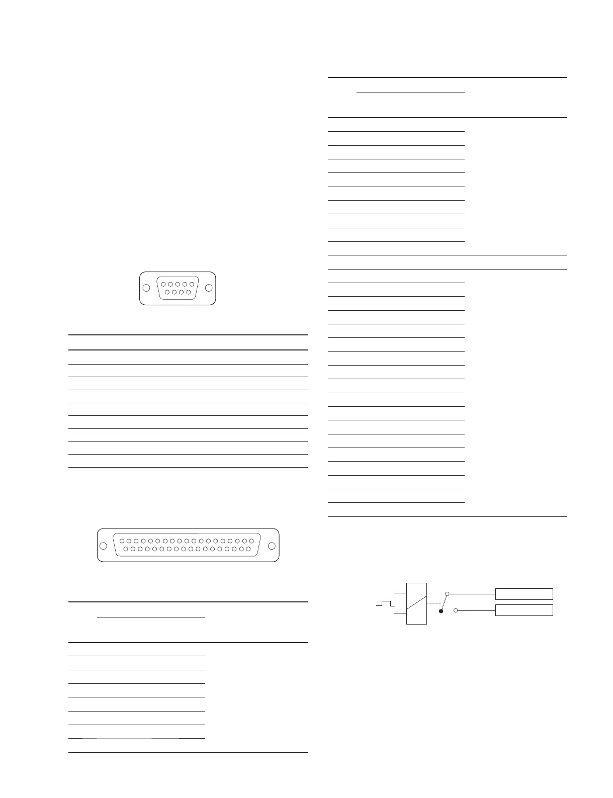
n
A and B of the same number constitute a pair of relay
contacts.
External View
1
5
69
1
20
19
37
External View
GPI OUT ) B
GPI OUT ) A
): 1-36
<Relay>
(1)

 Loading...


