ICP-X7000
1-34 (E)
Pin
No.
Signal Name Function
TALLY/
GPI OUT
1-18
TALLY/
GPI OUT
19-36
TALLY/
GPI OUT
37-54
15 OUT_15A OUT_33A OUT_51A General-
purpose
relay
output(A)
*1
16 OUT_16A OUT_34A OUT_52A
17 OUT_17A OUT_35A OUT_53A
18 OUT_18A OUT_36A OUT_54A
19 GND GND GND GND
20 OUT_1B OUT_19B OUT_37B General-
purpose
relay
output(B)
*1
21 OUT_2B OUT_20B OUT_38B
22 OUT_3B OUT_21B OUT_39B
23 OUT_4B OUT_22B OUT_40B
24 OUT_5B OUT_23B OUT_41B
25 OUT_6B OUT_24B OUT_42B
26 OUT_7B OUT_25B OUT_43B
27 OUT_8B OUT_26B OUT_44B
28 OUT_9B OUT_27B OUT_45B
29 OUT_10B OUT_28B OUT_46B
30 OUT_11B OUT_29B OUT_47B
31 OUT_12B OUT_30B OUT_48B
32 OUT_13B OUT_31B OUT_49B
33 OUT_14B OUT_32B OUT_50B
34 OUT_15B OUT_33B OUT_51B
35 OUT_16B OUT_34B OUT_52B
36 OUT_17B OUT_35B OUT_53B
37 OUT_18B OUT_36B OUT_54B
n
. A and B of the same number constitute a pair of relay
contacts.
. GPI input pins are pulled up on the board.
These pins can be connected to 3.3 V TTL or open-
collector output pins.
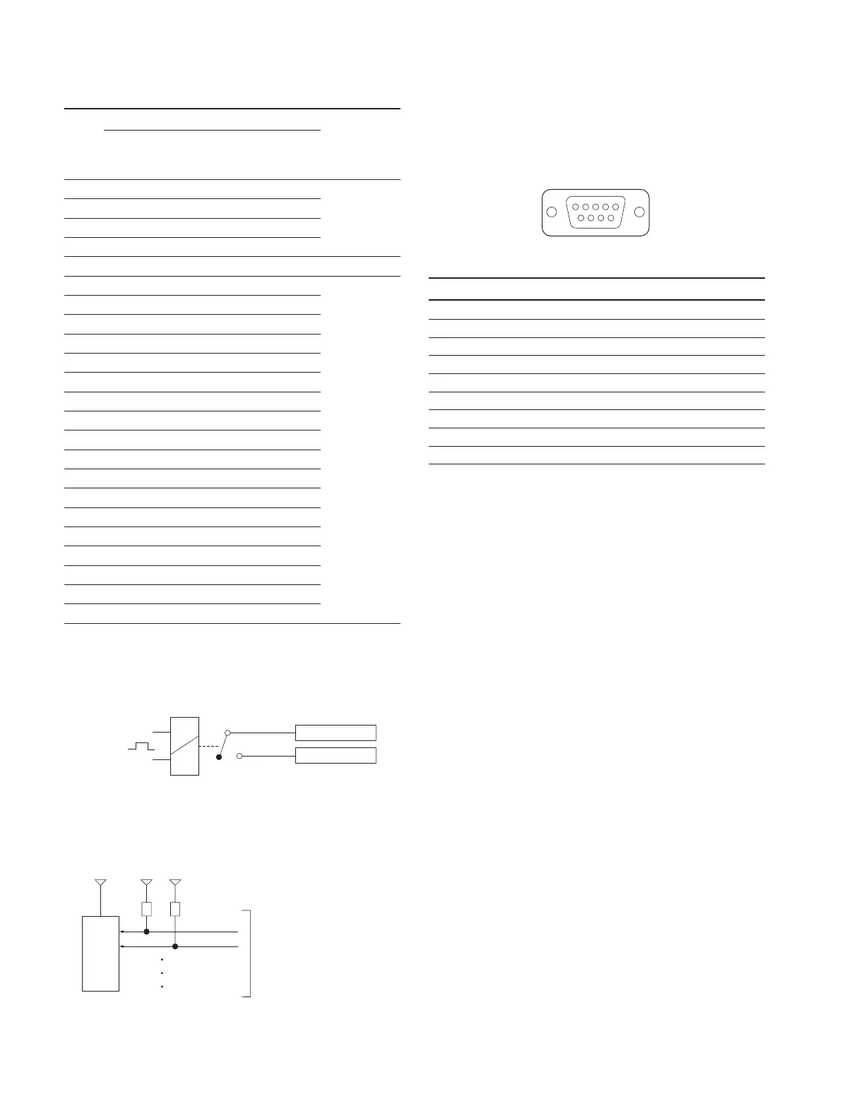
1-13-4. MKS-X7702
REMOTE1 to 6
D-sub 9pin, Female
Pin No. Signal Name Function
1 FG Frame ground
2 RX_ Received data (_)
3 TX+ Transmitted data (+)
4 GND Common ground
5 _ No Connection
6 GND Common ground
7 RX+ Received data (+)
8 TX_ Transmitted data (_)
9 FG Frame ground
GPI OUT ) B
GPI OUT ) A
): 1-54
<Relay>
(1)
External View
1
5
69
TTL
Buffer
3.3 V 3.3 V 3.3 V
Nȍ
GPI IN

 Loading...


