138
a) When the [ROT X] button is selected
b) When the [ROT Y] button is selected
For details about selecting the rotation direction, see
“Rotating a key (key control block)” (page 139).
Reducing, enlarging, moving, and rotating
keys (device control block)
Switch the device control block to resizer operation mode
to operate a two-dimensional transform.
1
Press the [M/E 1] button.
The [M/E 1] button is lit gree
n, and the device control
block switches to M/E-1 resizer operation mode.
You can select multiple swit
cher banks. The first
selected button becomes the reference channel, and is
lit green. Subsequent selected buttons are lit amber.
2
Press the [K1RSZ] button.
The [K1RSZ] button is lit green, and key 1 becomes
the target
of resizer operations.
You can select multiple keys. The first selected
bu
tton becomes the reference channel, and is lit
green. Subsequent selected buttons are lit amber.
3
Press the [RSZR ON] button.
The [RSZR ON] button turns
on and the resizer is
enabled.
4
Transform the key.
To change the aspect ratio of a key
Press the [ASP PERS] button,
turning it on, and
adjust the setting values using the trackball/Z-ring.
To change the position and size of a key
Press the [LOC SIZE] button, turning it on, and adjust
t
he setting values using the trackball/Z-ring.
To change the rotation and viewpoint position of a
ke
y
Press the [ROT] button, turning
it on, and adjust the
setting values using the trackball/Z-ring.
To finely adjust the setti
ng values of parameters
Press the [FINE] button, turning it on.
The adjustment mode switches t
o fine mode, enabling
fine adjustment of setting values using the trackball/
Z-ring.
To restrict the parameter
s targeted by the
operation
Press the [X] button, [Y] button, or [Z] button,
turning i
t on.
This enables operation only for the se
lected axis
using the trackball/Z-ring.
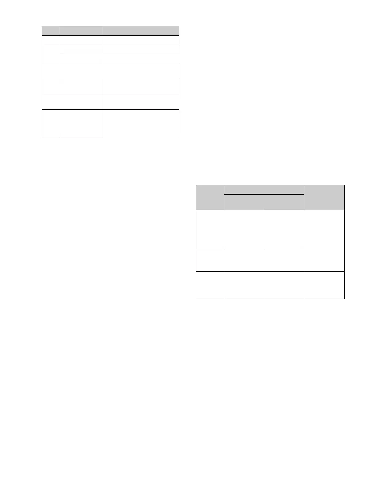
Transforming an image using trackball/Z-ring
operations
You can transform an image as foll
ows using trackball/Z-
ring operations for each two-dimensional transform.
Device control block display
In the device control block of the ICP-X7000, the display
shows the following information.
• Reference switcher bank name:
M/E1 to M/E5, P/P
• Reference resizer name: KEY1
RSZR to KEY8 RSZR
• Selected parameter name: ASP, LOC SIZE, ROT
PERS, BDR,
CROP
• X-axis, Y-axis, and Z-axis settin
gs (four edge settings
for crop)
To adjust the setting values of parameters using
the nume
ric keypad control block
You can press the [X] button, [Y] bu
tton, or [Z] button in
the device control block to display the name and value of
parameters on the display of the numeric keypad control
block and then set the X-axis, Y-axis, and Z-axis
parameters. Enter a value in the numeric keypad area and
press the [ENTER] button to apply the setting.
1-3 SIZE Size of key
1-4 ROT X Rotation around X-axis
a)
ROT Y Rotation around Y-axis
b)
1-5 PERS Viewpoint position
(perspective)
2-1 ASPECT X Aspect ratio in horizontal
direction
2-2 ASPECT Y Aspect ratio in vertical
direction
2-3 ASPECT R
Simultaneous adjustment of
aspect ratio in horizontal
direction and vertical
direction
No. Parameter Adjustment
Button Trackball Z-ring
Horizontal
direction
Vertical
direction
ASP
PERS
Change
aspe
ct ratio in
X-axis
direction
Change
aspect ratio in
Y-axis
direction
Simultaneous
change aspect
ratio in X-axis
direction and
Y-axis
direction
LOC
SIZE
Movement in
X-axis
dire
ction
Movement in
Y-axis
direction
Scaling
(shr
ink/
magnify)
ROT Rotation
arou
nd Y-axis
Rotation
around X-axis
Change
distance from
viewpoint
position