Digital Video Recorder
7
Chapter 3 — Configuration
NOTE: Your DVR should be completely installed before proceeding. Refer to Chapter 2 — Installation.
Front Panel Controls
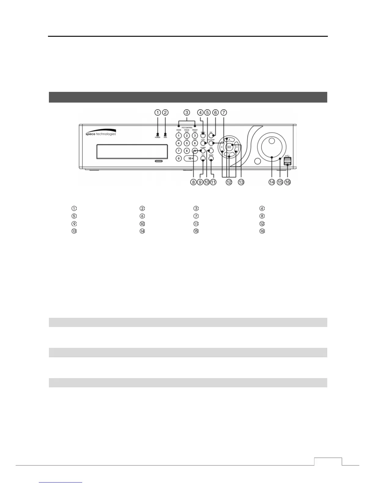
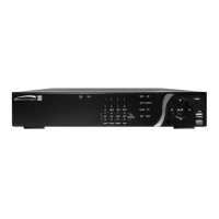
Figure 3 : 16-Channel DVR front panel.
Power LED HDD LED Camera Buttons Menu Button
Copy Button Esc Button Play/Stop Button Alarm Button
Sequence Button PTZ Button Mode Button Arrow Buttons
Enter Button Jog Dial Shuttle Ring USB Port
The front panel looks and operates much like a VCR combined with a multiplexer. The following describes each button
and control. Take a few minutes to review the descriptions. You will use these to initially set up your DVR and for
daily operations.
NOTE: The infrared sensor on the DVR is just to the left of the Jog Dial. Make certain that nothing blocks the
sensor, or the remote control will not function properly.
When you use wireless communication devices (such as Wi-Fi or Bluetooth) near the DVR, the remote
control might not function properly.
You can also use a USB mouse (not supplied) to navigate through the screens and menus much like you
would on a computer.
Power LED
The POWER LED is lit when the unit is On.
HDD LED
The HDD LED flickers when the DVR is recording or searching video on the hard disk drive.
Camera Buttons
Pressing the individual camera buttons will cause the selected camera to display full screen. Pressing the buttons 1 to
4 toggles the camera selection between local cameras and network cameras. For example, pressing the button 1 displays
the local camera number 1 and pressing the button 1 again displays the network camera number 1. Buttons are also
used to enter passwords.
NOTE: When selecting the camera channel from 10 to 16, press the 10+ and then 0 to 6.