Maintenance Waukesha Cherry-Burrell
®
Brand Universal 3 Pump
Page 30 95-03103 11/2018
Maintenance Inspections
The pump contains internal moving parts. DO NOT put hands or
fingers into the pump body ports or drive area at any time during
operation. To avoid serious injury, DO NOT install, clean, service,
or repair the pump unless all power is off and locked out and the
pump is de-pressurized. Shut off and drain product from the
pump prior to disconnecting the piping.
Detecting wear in the early stages can reduce repair costs and
down time. A simple “look-feel” inspection of the pump during
breakdown cleaning is recommended to detect signs of trouble at
an early stage.
A detailed maintenance inspection should be scheduled annually.
See “Annual Maintenance” on page 31.
Refer to the “Maintenance Inspection Chart” on page 32 for pos-
sible causes and solutions to common issues discovered during
inspection.
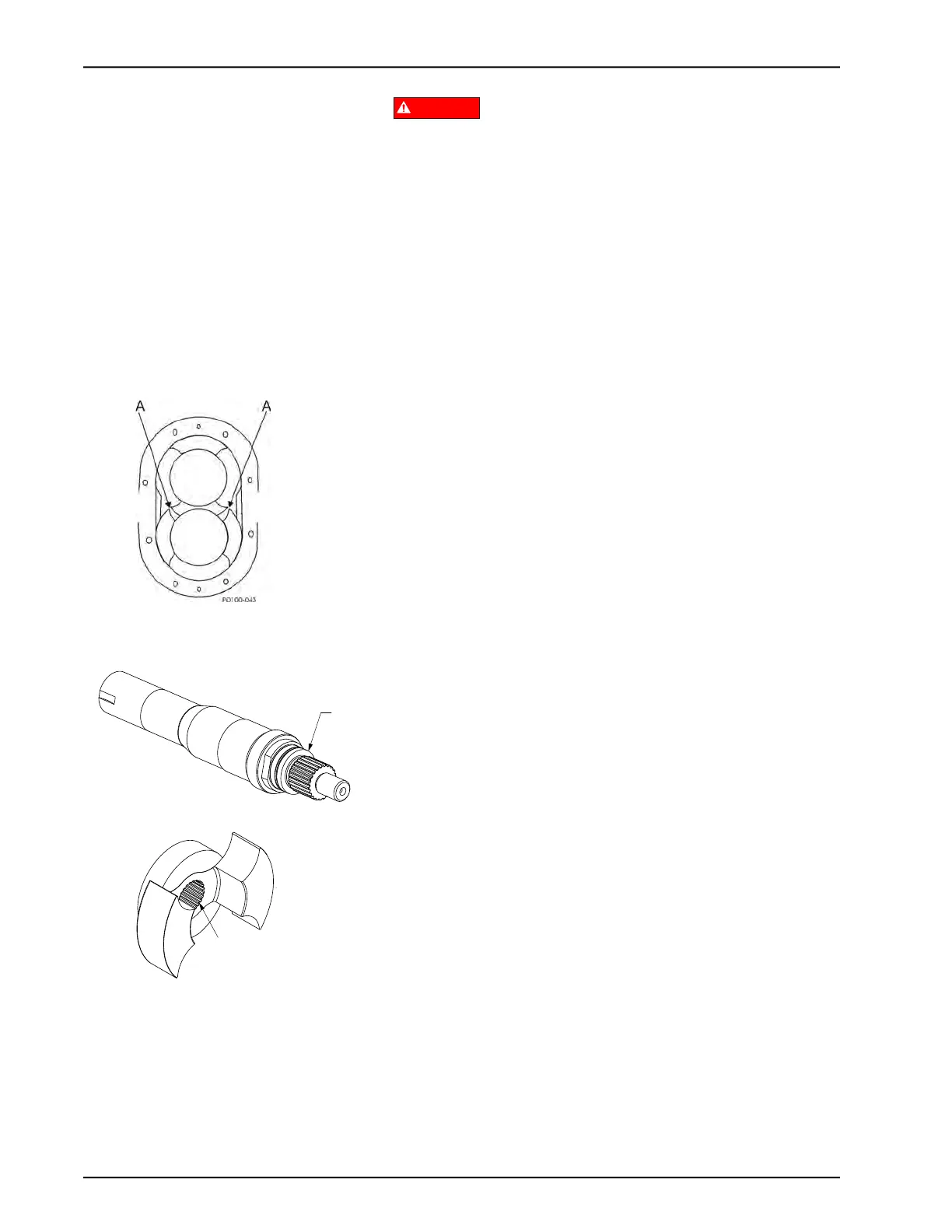
Inspection of Rotor Tips
Remove the cover (see “Remove Cover” on page 34) and check
for metal-to-metal contact between the rotor wings. When contact
is detected, repair or replace the pump.
Visually inspect the rotors for rotor tip to rotor tip contact and rotor
tip to rotor hub contact. Manually rotate the pump drive shaft and
ensure that the rotor tip clearance is equal on both sides as indi-
cated in Figure 31.
Inspection of Shaft and Shaft Shoulder
Visually inspect the shaft for twists or bends; replace it as neces-
sary. Visually inspect the shaft shoulder (Figure 32, item C) for
excessive wear; replace it as necessary. If the shaft shoulder has
a sharp edge, remove the edge with a file to prevent cutting the
shaft O-ring on installation.
Inspection of Rotor
Visually inspect the rotors for worn splines (Figure 32, item A)
and hub wear at the rotor stress points (see arrows in Figure 33
on page 31). Each time the rotors are removed, replace the prod-
uct side seal O-rings.
NOTE: Rotor hub and shaft shoulder wear are caused by
operating with a loose rotor nut(s) for extended periods.
Figure 31 - Rotor to Rotor Tip
Clearance
Figure 32 - Shaft and Rotor Inspection