Waukesha Cherry-Burrell
®
Brand Universal 3 Pump Maintenance
11/2018 95-03103 Page 89
16. Grease the front and rear bearing through the grease fittings
until grease is visible around the bearing assemblies. The
amount of grease required is listed in “Grease Quantity (per
Bearing)” on page 29. Rotate the shafts while greasing to
disperse the grease.
17. Lubricate the seal lips and install the grease seals in the
bearing retainers (compression spring on inside).
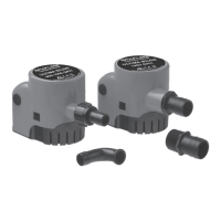
18. Coat the retainer flanges with silicone sealant (Figure 212,
item A). (Gore-Tex
®
sealing tape can be used on silicone free
models.) The grease seal (item 14) will be flush with the front
of the bearing retainer. On 030 models, the grease seal will
be against the step on the inside diameter of the retainer.
19. Install the bearing retainers (Figure 212, item 32).
Install Rear Seal Assembly
NOTE: Place tape or other material over the shaft end to prevent
cutting the seal during installation.
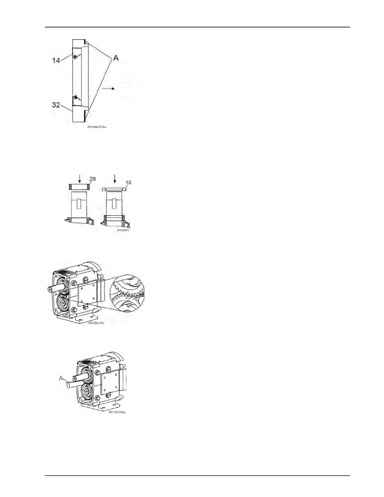
1. Install the gear spacers (Figure 213, item 29).
2. Lubricate the inside and outside diameters of the oil seals
with oil or grease.
3. Install the oil seals with the spring facing out (Figure 213,
item 13).
Install Timing Gears
1. Place the gear keys into the shaft key slots. Angle the keys
out for easier installation of the gears.
NOTE: To aid in timing setup, rotate the rotors until they are
at right angles to each other before installing the gears.
2. Slide the spur drive gear onto the drive shaft. The spur drive
gear has one punch mark on the gear.
3. Slide the short shaft gear onto the short shaft. The short shaft
gear has two punch marks on the gear. Straddle the single
punch mark of the spur drive gear with the two punch marks
on the short shaft gear (Figure 214).
4. Use a wood or nylon block (Figure 215, item A) to keep the
shafts from turning. If a block is not available, use rags to
block the gears, or with one rotor on the shaft, block the rotor
with a nylon dowel.
5. Slide the lock washers onto the shaft. Lubricate the threaded
area on the shafts and face of the locknuts with oil or grease.
Figure 212 - Install Bearing Retainer
Gear case
Figure 213 - Install Rear Seal
Figure 214 - Timing Gear Marks
Figure 215 - Block Shaft Rotation