Waukesha Cherry-Burrell
®
Brand Universal 3 Pump Installation
11/2018 95-03103 Page 19
Install Connections and
Piping
These pumps are positive displacement design and will be
severely damaged if operated with closed valves in discharge or
inlet lines. The pump warranty is not valid for damages caused by
a hydraulic overload from operation or start-up with a closed
valve in the system.
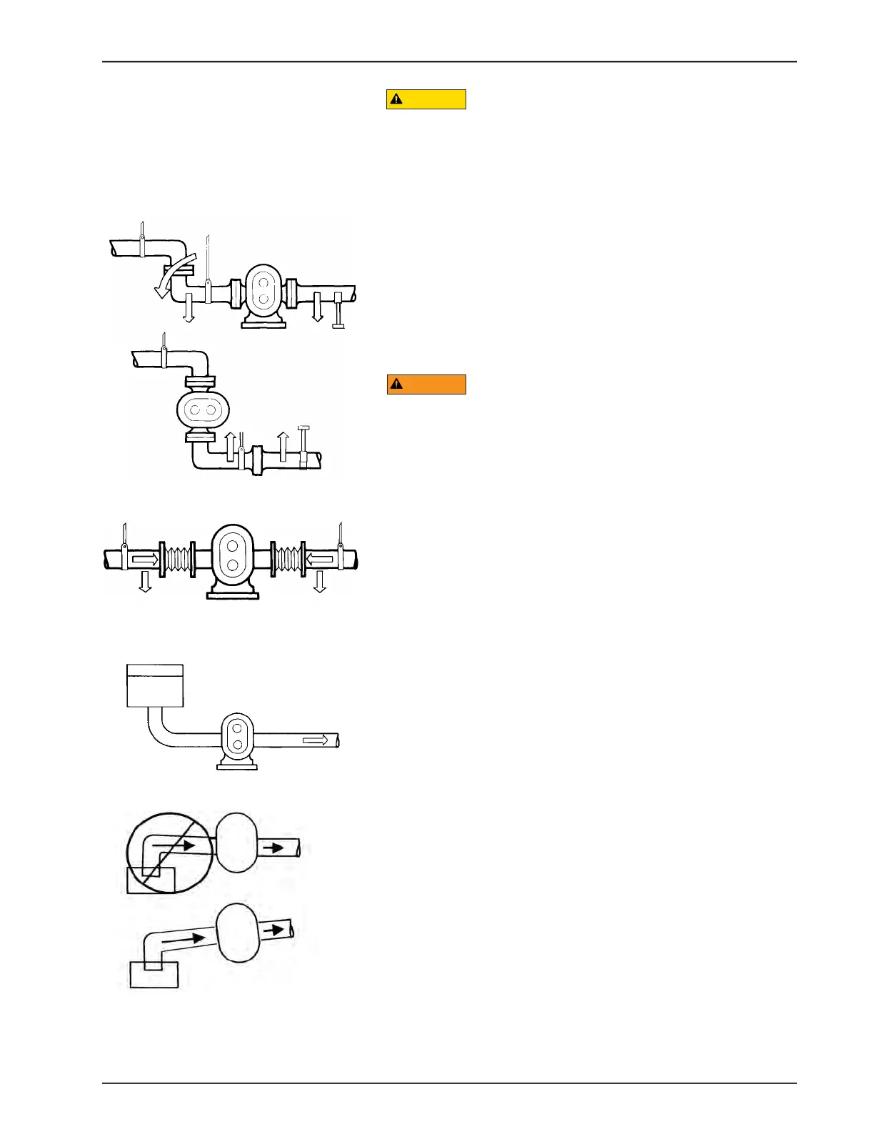
Piping Support
To minimize forces exerted on the pump, support all piping to the
pump independently with hangers or pedestals. Such forces can
cause misalignment of the pump parts and lead to excessive
wear of rotors, bearings, and shafts.
Figure 8 shows typical supporting methods used to independently
support each pipe, reducing the weight effect of piping and fluid
on the pump.
Do not exceed 50 lb (22.7 kg) load on pump inlet or discharge
ports. Exceeding this limit may cause damage to the pump.
Expansion Joints
Thermal expansion of piping can cause tremendous forces. Use
thermal expansion joints to minimize these forces on the pump.
Flexible joints can be used to limit transmission of mechanical
vibration. Ensure that the free ends of any flexible connections in
the system are anchored.
Inlet Piping
Install the pump below the supply liquid level to reduce the air in
the system by flooded suction, to prevent the pump from becom-
ing air-bound (Figure 10).
If the pump is installed above the supply liquid level, the piping on
the inlet side must slope up toward the pump, preventing air
pockets in the pipes (Figure 11).
Figure 8 - Piping Support
Figure 9 - Flexible Connections and
Supports
Figure 10 - Pump Below Supply
Recommended
Figure 11 - Piping Slope
NOT recommended
Recommended