Installation Waukesha Cherry-Burrell
®
Brand Universal 3 Pump
Page 18 95-03103 11/2018
Install the pump and piping system in accordance with local
codes and restrictions. Practices described in this manual are
recommended for optimum performance.
The motor must be installed by qualified personnel, e.g., a
licensed electrician.
All system equipment, such as motors, sheaves, drive couplings,
speed reducers, etc., must be properly sized to ensure satisfac-
tory operation of your Waukesha Cherry-Burrell brand pump
within its limits. Customer-supplied motors should have a basic
level of safety to prevent electrical hazards, and should be dealt
with in accordance with the manufacturer's instructions.
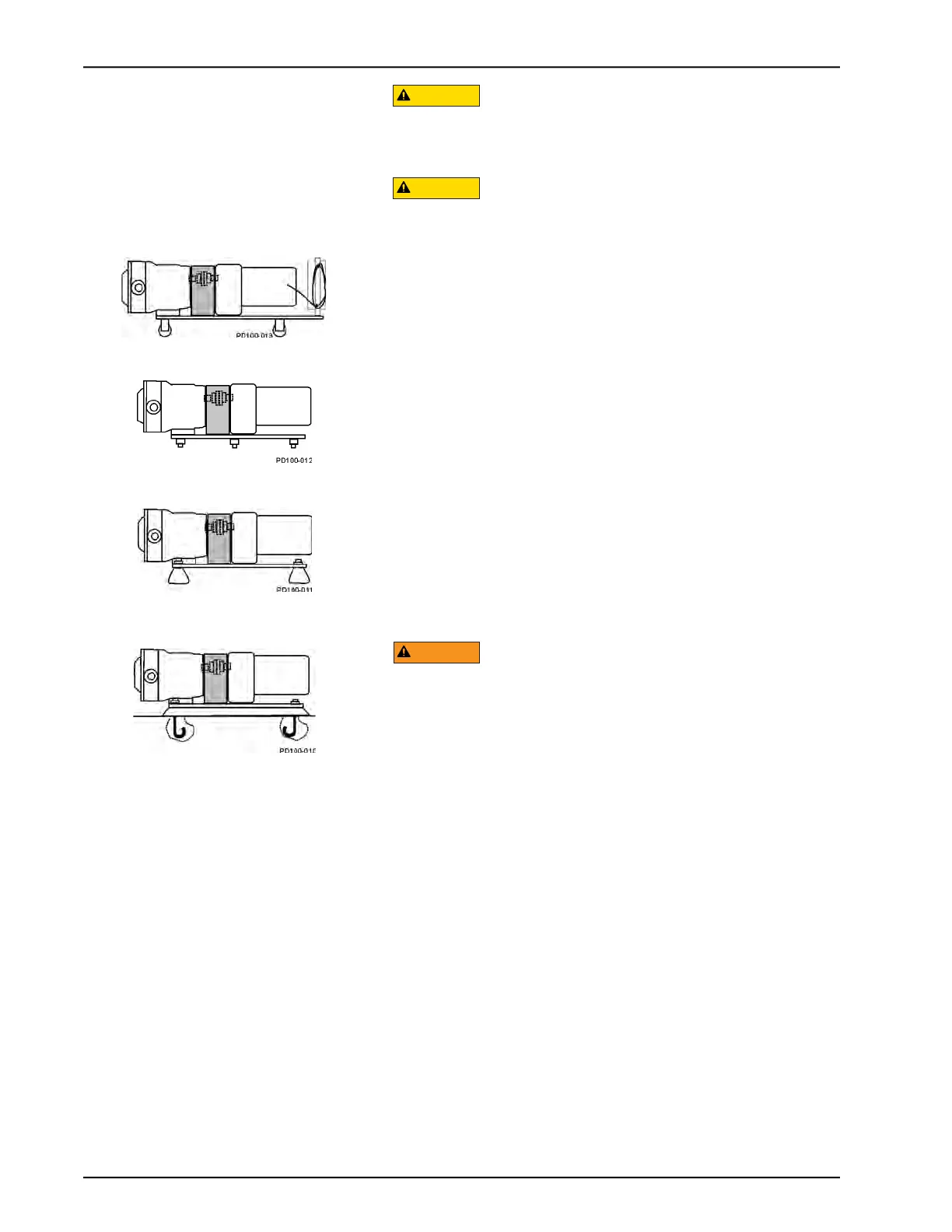
In a typical installation configuration, the pump and drive unit are
mounted on a common base plate. The unit can be installed in
any of the arrangements shown in Figure 4 through Figure 7.
NOTE: The gap between the pump body and gear case is
required for 3-A sanitary standards.
NOTE: When installing a unit as shown in Figure 7, level the unit
before installing the bolts.
The shaded area in Figure 4 through Figure 7 indicates the guard
location.
See “Pump Shaft Guards” on page 101.
Full guards must be installed to isolate operators and
maintenance personnel from rotating components.
Guards are provided as part of a complete pump and drive
package and are selected by SPX FLOW Engineering for the
pump, base, and motor ordered. Do not modify the guard
provided by SPX FLOW. If the guard provided by SPX FLOW is
lost, contact SPX FLOW Customer Service and provide your
order number or PO number of the pump to order a correctly-
sized replacement guard.
If the pump was not purchased as a unit, it is the responsibility of
the customer to ensure proper guarding. Refer to your local
regulations for guidance.
Figure 4 - Portable Base
Figure 5 - Adjustable Leg Base
Figure 6 - Leveling and/or Vibration
Isolation Pads
Figure 7 - Permanent Installation on
Foundation