Operational amplifier (OPAMP)
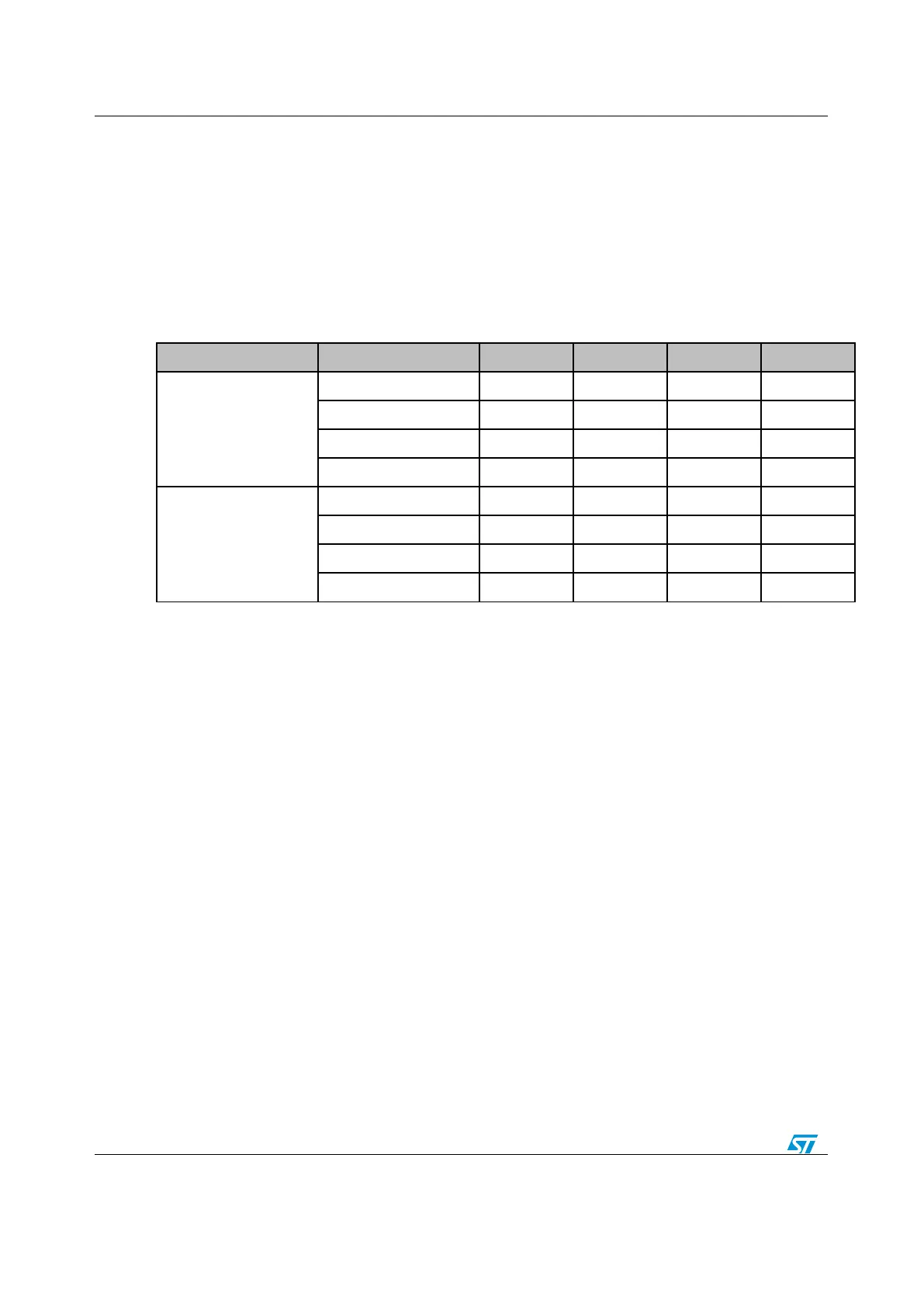
The OPAMPs non inverting input can be selected among the list shown by table
below.
The OPAMPs inverting input can be selected among the list shown by table below.
The OPAMPs outputs can be internally connected to the inverting input (follower
mode)
The OPAMPs outputs can be internally connected to resistor feedback output
(Programmable Gain Amplifier mode)
The OPAMPs outputs can be internally connected to ADC
The OPAMPs can be calibrated to compensate the offset compensation
Timer-controlled Mux for automatic switch of inverting and non-inverting input
Table 14: OPAMPs inverting/non-inverting inputs
16.2.2 How to use this driver
This driver provides functions to configure and program the OPAMP of all STM32F30x
devices. To use the OPAMP, perform the following steps:
1. Enable the SYSCFG APB clock to get write access to OPAMP register using
RCC_APB2PeriphClockCmd(RCC_APB2Periph_SYSCFG, ENABLE);
2. Configure the OPAMP input in analog mode using GPIO_Init()
3. Configure the OPAMP using OPAMP_Init() function:
Select the inverting input
Select the non-inverting inverting input
4. Enable the OPAMP using OPAMP_Cmd() function
16.2.3 Initialization and Configuration functions
OPAMP_DeInit()
OPAMP_Init()
OPAMP_StructInit()
OPAMP_PGAConfig()
OPAMP_VrefConfig()
OPAMP_VrefConnectNonInvertingInput()
OPAMP_VrefConnectADCCmd()
OPAMP_TimerControlledMuxConfig()
OPAMP_TimerControlledMuxCmd()
 Loading...


