Selects the output polarity of the comparator. This parameter can be a value of
COMP_OutputPoloarity
uint32_t COMP_InitTypeDef::COMP_Hysteresis
Selects the hysteresis voltage of the comparator. This parameter can be a value
of COMP_Hysteresis
uint32_t COMP_InitTypeDef::COMP_Mode
Selects the operating mode of the comparator and allows to adjust the
speed/consumption. This parameter can be a value of COMP_Mode
5.2 COMP Firmware driver API description
The following section lists the various functions of the COMP library.
5.2.1 COMP Peripheral features
The device integrates 7 analog comparators COMP1, COMP2...COMP7:
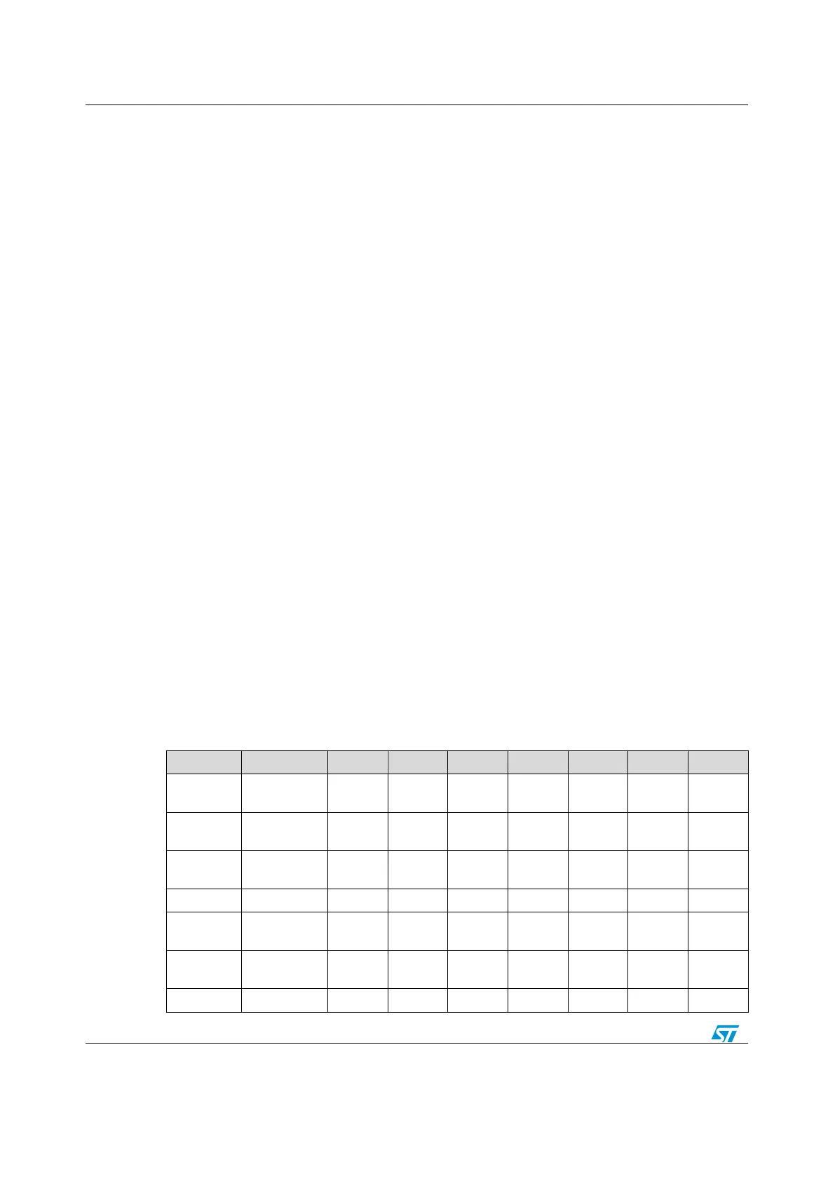
1. The non inverting input and inverting input can be set to GPIO pins as shown in
table1. COMP Inputs below.
2. The COMP output is internally is available using COMP_GetOutputLevel() and can be
set on GPIO pins. Refer to table 2. COMP Outputs below.
3. The COMP output can be redirected to embedded timers (TIM1, TIM2, TIM3...) Refer
to table 3. COMP Outputs redirection to embedded timers below.
4. The comparators COMP1 and COMP2, COMP3 and COMP4, COMP5 and COMP6
can be combined in window mode and only COMP1, COMP3 and COMP5 non
inverting input can be used as non-inverting input.
5. The seven comparators have interrupt capability with wake-up from Sleep and Stop
modes (through the EXTI controller):
COMP1 is internally connected to EXTI Line 21
COMP2 is internally connected to EXTI Line 22
COMP3 is internally connected to EXTI Line 29
COMP4 is internally connected to EXTI Line 30
COMP5 is internally connected to EXTI Line 31
COMP6 is internally connected to EXTI Line 32
COMP7 is internally connected to EXTI Line 33
Table 10: COMP Inputs
 Loading...


