DOCUMENT NUMBER:
L500-912.820 ISSUE JUL 20, 2016
AMENDMENT: 00
DATE:
CHAPTERPAGE 68
MAINTENANCE MANUAL STEMME S12
6.4 FLIGHT CONTROL SYSTEM
6.4.1 DEFLECTION OF CONTROL SURFACES, CONTROL SYSTEM FRICTION, AND
CONTROL FORCES
After any adjustment or assembly work on the control system, control deections, friction and
forces in the control system must be measured.
For measurement procedures see form Rigging Report (Annex D). Rated values.
6.4.1.1 CONTROL SURFACE DEFLECTIONS
ELEVATOR
Measuring point is trailing edge of inner rib of elevator (140 mm / 5.51 in from hinge line).
Full Deection
- 44
+2
/
-5
mm + 44
+5
/
-2
mm
(-1.73
+0.08
/
-0.2
in) (+1.73
+0.2
/
-0.08
in)
RUDDER
Measuring point is lower rear corner of control surface (420 mm / 16.5 in. from hinge line).
Full Deection
+220 ± 15 mm -220 ± 15 mm
(+8.7 ± 0.6 in) (-8.7 ± 0.6 in)
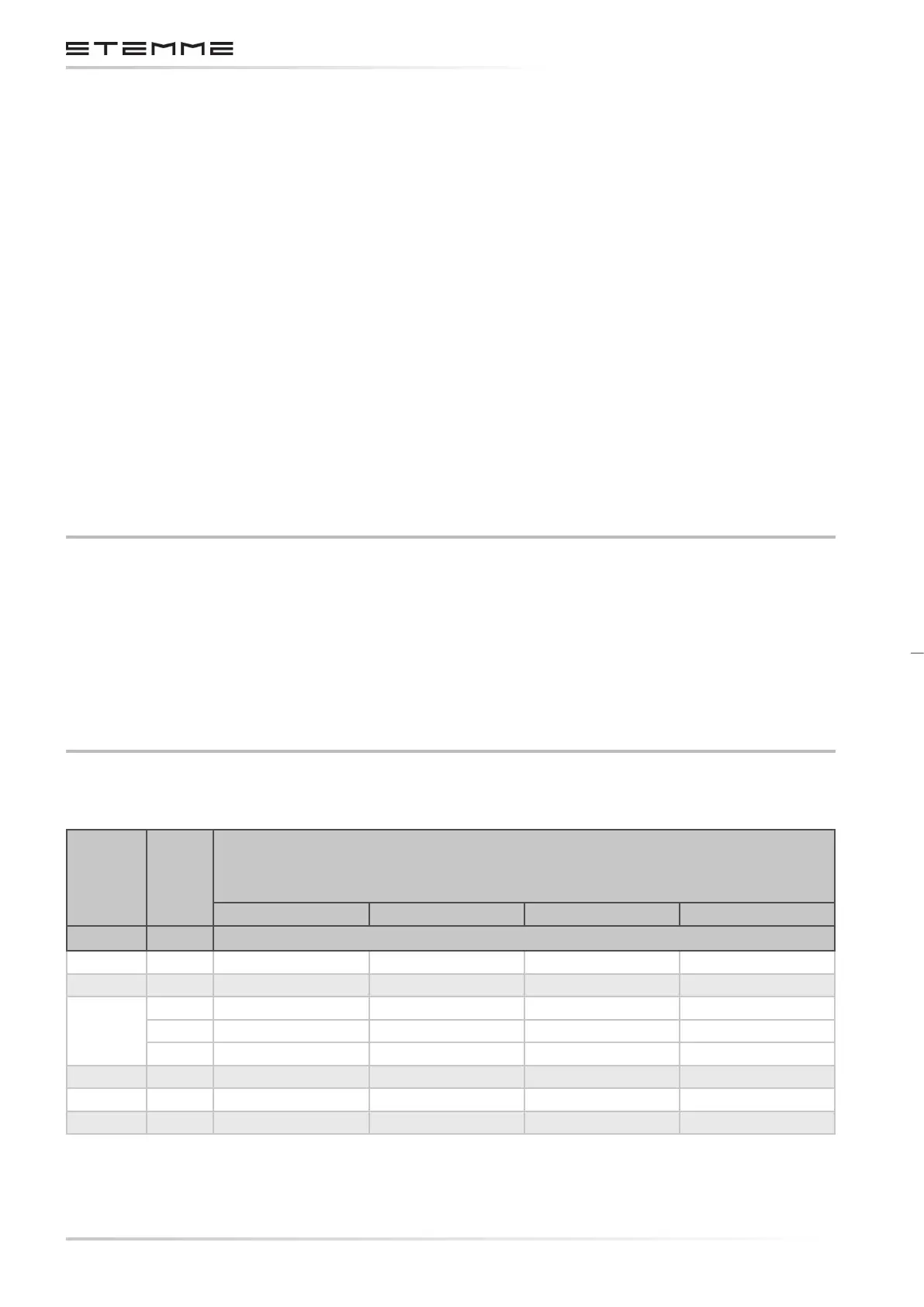
WING FLAPS AND AILERONS
Flap Lever Control
Stick
Measurement points
1) Aileron: Inner rib of the control surface, 163 mm / 6.42 in. from hinge line.
2) Wing ap: Inner rib of the control surface, 175 mm / 6.89 in. from hinge line.
left aileron left wing ap right wing ap right aileron
Position Position mm (in.)
- 10° neutral -31 ± 4 (-1.22 ± 0.16) -31 ± 4 (-1.22 ± 0.16)
- 5° neutral -15 ± 4 (-0.6 ± 0.16) -15 ± 4 (-0.6 ± 0.16)
0
left -48 ± 4 (-1.89 ± 0.16) +27 ± 3 (+1.06 ± 0.12)
neutral 0 ± 2 (0 ± 0.08) 0 ± 2 (0 ± 0.08) 0 ± 2 (0 ± 0.08) 0 ± 2 (0 ± 0.08)
right +27 ± 3 (1.06 ±0.12) -48 ± 4 (-1.89 ±0.16)
+ 5° neutral +15 ± 4 (+0.6 ± 0.16) +15 ± 4 (+0.6 ± 0.16)
+ 10° neutral +31 ± 4 (+1.22 ± 0.16) +31 ± 4 (+1.22 ± 0.16)
L (+16°) neutral +51 ± 4 (+2 ± 0.16) +51 ± 4 (+2 ± 0.16)
Empty eld: No measure to be checked.