DOCUMENT NUMBER:
L500-912.820 ISSUE JUL 20, 2016
AMENDMENT: 00
DATE:
CHAPTERPAGE 354
MAINTENANCE MANUAL STEMME S12
3.7.17.3 OPERATION
The oil temperature indication system does not require operation actions by the pilot. Scale
markings of operational limits and instructions to the pilot about corrective actions in the case
of exceeded limits are dened in the AFM.
3.7.18 FUEL DISTRIBUTION SYSTEM ATA 282000
3.7.18.1 DESCRIPTION
The fuel is stored in two wing tanks of equal size, one in each side of the wing center section. Each
tank is vented to the atmosphere to prevent overpressure or vacuum situations. Each tank has
an over wing fuel ller. Each tank is connected via a coarse lter and quick drain to a dedicated
electric plunger pump with downstream check valves. These check valves close o the fuel line
when the pumps are not powered. The transfer pumps deliver the fuel into the feeder tank. The
fuel line between check valves and feeder tank includes a quick-disconnect to facilitate handling
during wing rigging and de-rigging.
The feeder tank incorporates two oat switches to control the transfer pumps and to generate a
low fuel warning signal to the pilot. From the feeder tank the fuel is delivered by a turbine pump
(feeder pump) to the fuel pressure regulator, which provides the required fuel pressure to the
carburetors. The regulator’s return line ends in the feeder tank.
The feeder pump is backed up by another turbine pump of the same type.
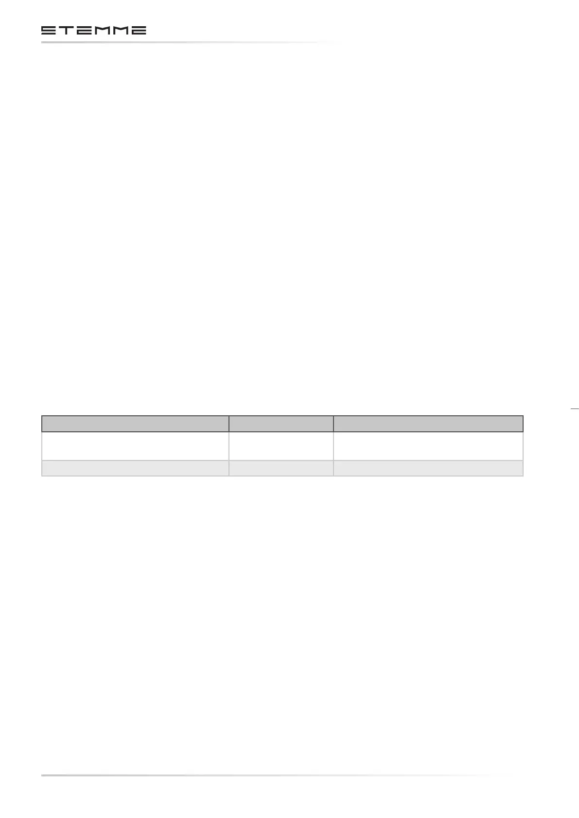
3.7.18.2 PARTS SPECIFICATION
Part STEMME p/n Manufacturer p/n
Main and Auxiliary Feeder Pump
11AB-M02
(830.209)
Pierburg E1F
Fuel Transfer Pumps 830.521 HKT HEP-02
3.7.18.3 OPERATION
a) Main Feeder Pump Control
The main boost pump is supplied by the engine’s electrical system. It automatically starts to work
when the engine’s electrical system is activated by the pilot. Proper operation of the main boost
pump is indicated by the fuel pressure indicating system (refer 28-44-00). The electrical power
line of the main feeder pump is protected by a fuse located inside the engine system junction box
(refer 24-60-00).
b) Auxiliary Feeder Pump Control
The auxiliary boost pump is controlled by a switch to be manually activated by the pilot when
required. To achieve better redundancy of the fuel system, the auxiliary boost pump is powered by
the main electrical system, independently from the engine’s electrical system. The proper func-
tion of the auxiliary boost pump is indicated by a green light and by the fuel pressure indicating
system (ref 28-44-00). The electrical power line of the auxiliary boost pump is protected by a fuse
located inside the main system junction box (refer 24-60-00).