DOCUMENT NUMBER:
L500-912.820 ISSUE JUL 20, 2016
AMENDMENT: 00
DATE:
CHAPTERPAGE 71
MAINTENANCE MANUAL STEMME S12
7. MAINTENANCE INSTRUCTIONS, TOLERANCES AND ADJUSTMENT
DATA FOR ASSEMBLIES / EQUIPMENT
7.1 AIRFRAME
7.1.1 WING
Description: See section 3.1.1
Lubrication: See section 6.5
7.1.1.1 CRACKS AND STRUCTURAL DAMAGE
•
Check wings for cracks and abnormal surface (local buckles, roughness, holes and delami-
nation), especially near to force transmission points (ttings, control links, ap hinges) and
at the division areas of inner and outer wing as well as of outer wing and wing extension.
See also section 6.6 and Annex A Small Repairs of Composite Materials.
7.1.1.2 DRAINAGE AND VENTILATION HOLES
• Check holes for cleanness and for uid outow; clean if necessary. Fuel trails found may
indicate fuel tank leakage. The holes are located next to the air brakes, fuel tanks and next
to the wing root of inner and outer wing and wing extension (see position plan in section
6.7).
7.1.1.3 WING FITTINGS
•
Check backlash of the wing ttings by moving wing tips forward and aft and up and down.
If excessive backlash is found or in case of doubt the bolts and ttings must be measured
by means of a micro meter.
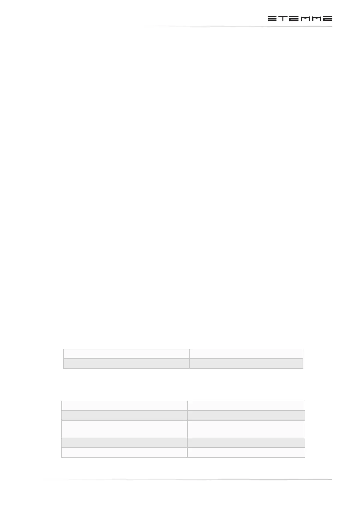
CLEARANCE OF WING/FUSELAGE ATTACHMENTS
Axial Maximum 0.4 mm / 0.016 in
Radial Maximum 0.15 mm / 0.006 in
CLEARANCE OF INNERTOOUTER WING ATTACHMENTS
Front and rear bolts, axial Maximum 0.3 mm / 0.012 in each
Front and rear bolts, radial Maximum 0.2 mm / 0.008 in each
Main bolt, radial Maximum of 0.15 mm / 0.006 in
in the bearings of spar boxes.
Spar stub bolts axial Maximum 2 mm / 0.08 in
Spar stub bolts radial Maximum 0.2 mm / 0.008 in