DOCUMENT NUMBER:
L500-912.820 ISSUE JUL 20, 2016
AMENDMENT: 00
DATE:
CHAPTERPAGE 35
MAINTENANCE MANUAL STEMME S12
3.2.3 CONTROLS AT THE INSTRUMENT PANEL
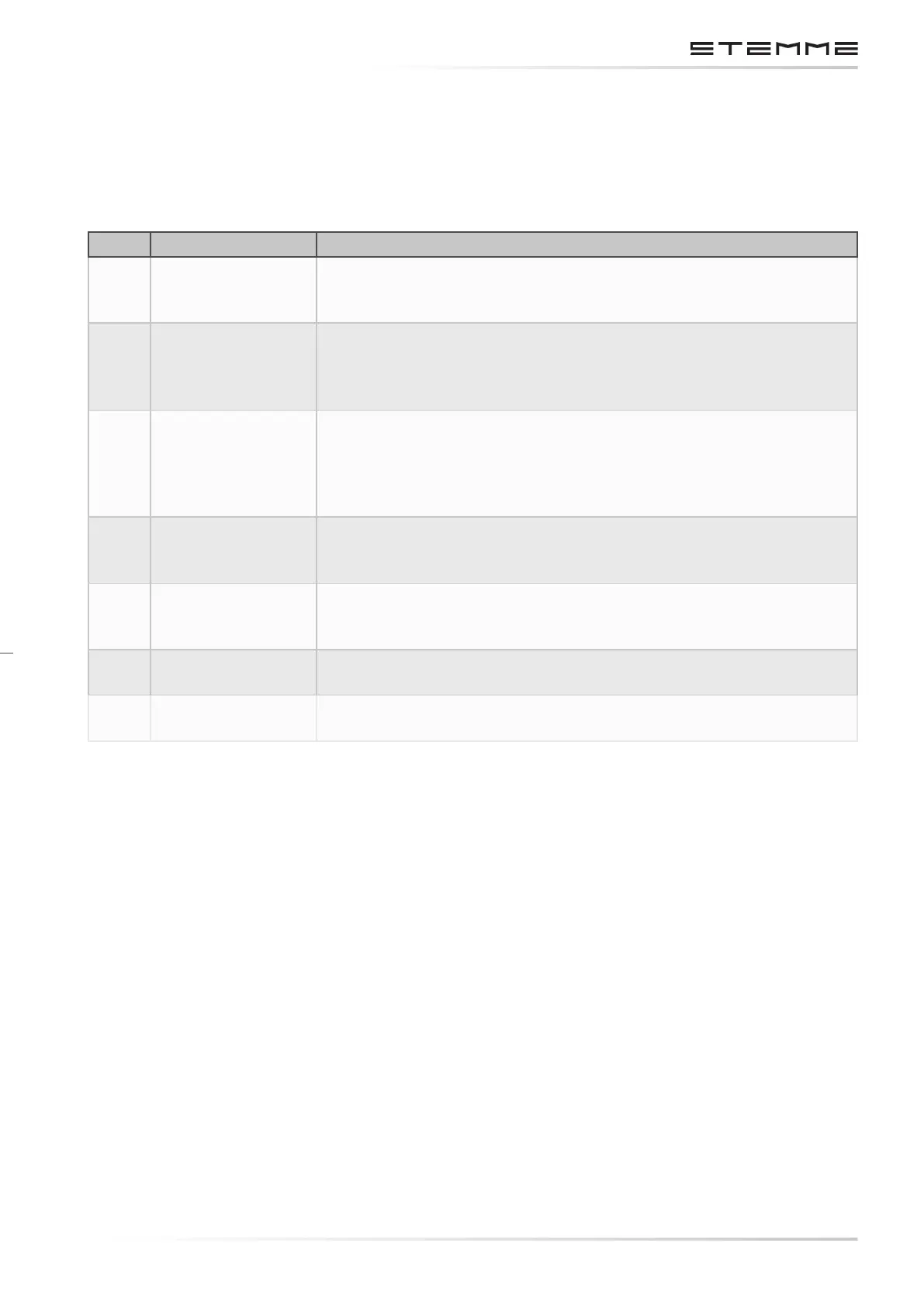
The following overview includes controls in the lower area of the instrument panel. These elements
are included in gure 3.2.3.a Arrangement of Elements on the Instrument Panel, see section
3.2.4.
No. Name of Control Airframe Position
1. Emergency Canopy
Release
Red pull-handle on LH side of the switch panel. It is pulled for emer-
gency canopy jettison after opening the canopy locks on LH or RH
side of the canopy frame.
2. Cowl Flap
Adjustment
Black T-handle on LH side of the lower middle section of the in-
strument panel to reduce engine cooling in cruise condition. The
foremost position means cowl aps fully OPEN, 5 settings aft are
available to reduce the opening of the cowl aps.
3. Nose-cone
Operation
Black handle in the bottom center of the instrument panel to open,
close and lock the nose-cone, linked to the engine electric master
switch. Unlock by lifting, lock by pushing down the handle. In the
forward position (Nose-cone OPEN) the engine master switch turns
ON when nose-cone is LOCKED.
4. Propeller Brake Black T-handle to the RH side of the cowl ap adjustment to brake
the propeller to a full stop after engine has been switched o in
ight. Braking is by pulling the handle.
5. Propeller
Positioning
Black T-handle to the RH side of the propeller brake to position the
propeller to t within the nose-cone contour. Operation is by a slow
and steady pull on the handle to its stop.
6. Air Vents Two adjustable air vents for cockpit ventilation, one on LH and one
on RH side of the Instrument panel, are provided.
7. Canopy
Ventilation
Knob on RH side of the ignition/starter switch to ventilate the can-
opy. The pulled position means canopy ventilation OPEN.
3.2.4 INSTRUMENT PANEL
The following description gives an overview of instruments, controls, monitor devices and CB’s
installed on the instrument panel. The minimum Equipment List of the S12 Aircraft Fligth Manual
is relevant.
The positions of the elements are shown in gure 3.2.3.a Arrangement of Elements on the In-
strument Panel, valid for the aircraft serial number as indicated on the title page of this Aircraft
Maintenance Manual.
The ight control instruments include at least
1. One ASI (airspeed range 50 – 300 km/h / 27 – 162 kt),
2. One Altimeter,
3. One magnetic compass,
4. Trim indicator display.
These instruments are located directly in the view area of the PIC (in front of LH seat). Dual in-
strumentation is possible to provide an optimum view on ight control instruments from the RH