DOCUMENT NUMBER:
L500-912.820 ISSUE JUL 20, 2016
AMENDMENT: 00
DATE:
CHAPTERPAGE 334
MAINTENANCE MANUAL STEMME S12
MAIN LANDING GEAR EMERGENCY EXTENSION
By pulling two T-handles in the cockpit, one after the other, the landing gear actuators are dis-
connected from the locking elbow struts by means of Bowden cables and the landing gear legs
extend by gravity to the “gear down” position. The secure locking of each leg in the extended
position is achieved by a spring that forces the over-center strut into its over-center position.
In case of emergency extension the two legs should be released in the recommended sequence
(T-handles marked 1 & 2, wrong order is not critical). The RH gear strut is equipped with a mech-
anism to avoid jamming of the struts in case of an incorrect sequence.
3.5.2 TAIL WHEEL
The tail wheel is not sprung and ts in a trailing fork mounted in two bearings. The upper bearing
is a combined radial/axial sleeve bearing. The journal is constructed so that a certain friction
damping is produced at the axial sleeve surfaces when loaded in axial direction in order to avoid
tail wheel utter whilst taxiing. For steering on the ground the tail wheel fork is coupled with the
rudder by means of two pre-loaded tension springs.
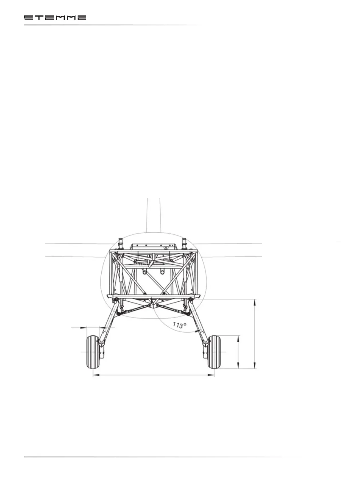
Figure 3.5.1.a
Main Landing Gear
1360 mm / 53.54 in
139 mm / 5.47 in
779 mm / 30.67 in
372 mm / 14.64 in