DOCUMENT NUMBER:
L500-912.820 ISSUE JUL 20, 2016
AMENDMENT: 00
DATE:
CHAPTERPAGE 345
MAINTENANCE MANUAL STEMME S12
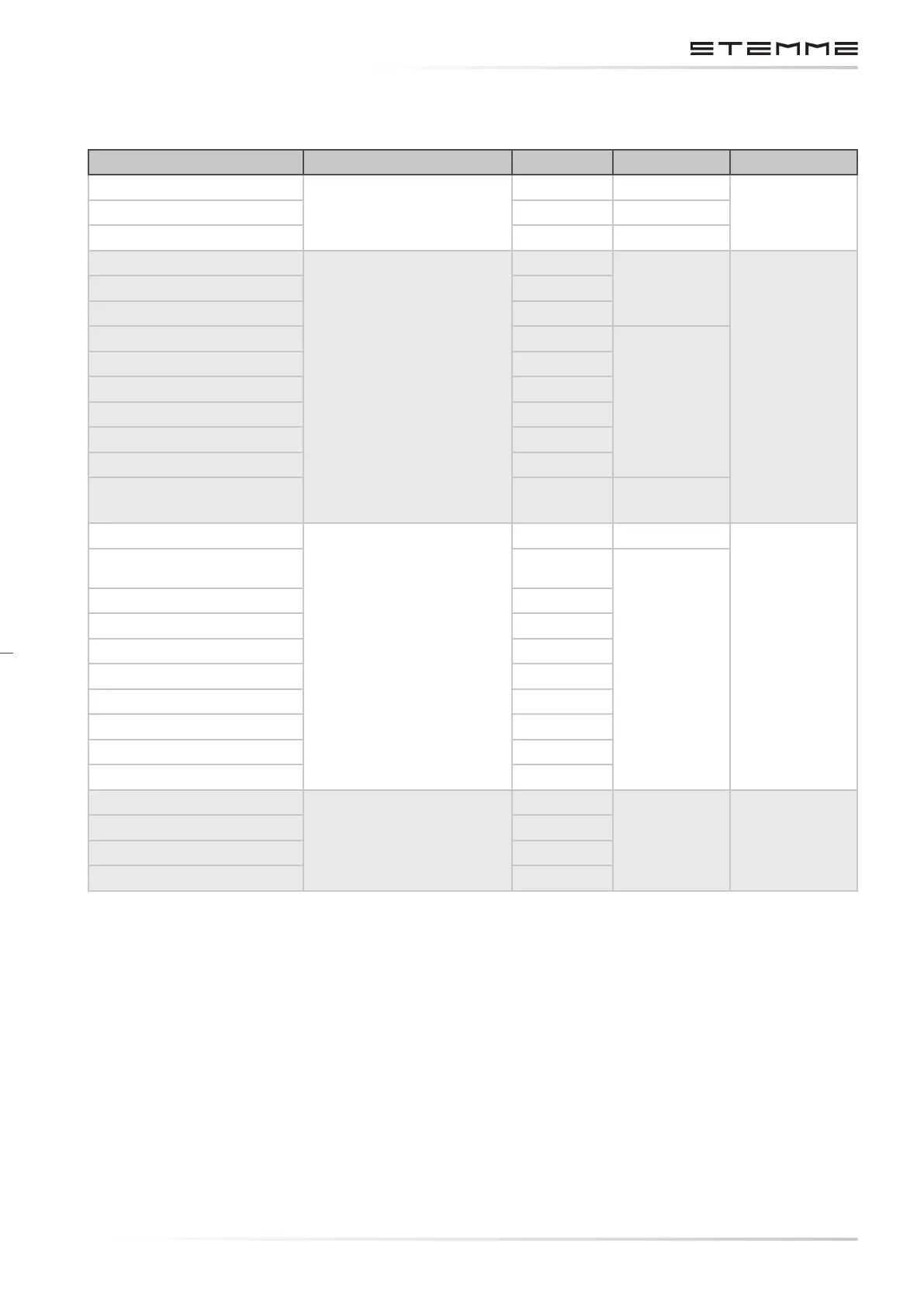
3.7.6.5 FUSE SPECIFICATIONS: ENGINE SYSTEM
Circuit Location of Fuse/CB Rating (A) STEMME p/n Qualication
Starter
Engine System Box
80 831.491
ISO 8820-5External Power Supply 80 831.491
System Master Fuse 50 831.247
Engine Bus Supply
Fuse holder Engine
System Box
15
831.432
ISO 8820-3
Internal Generator 15
Prop Pitch Control Power 15
Main Fuel Pump 5
831.430
TCU Power 5
Fuel Transfer Pump RH 5
Fuel Transfer Pump LH 5
Ammeter Hi 5
Ammeter Lo 5
Internal Generator
warning
2 831.429
Starter Relay
Fuse holder Instrument
Panel
5 831.430
ISO 8820-3
Propeller Pitch Indication 2
831.429
Low Fuel Warning Light 2
Tachometer 2
Ignition retarder 2
Fuel Pressure Indicator 2
Fuel Level Indicator Left 2
Fuel Level Indicator Right
Oil Press + CHT Left 2
Oil Temp + CHT Right 2
Fuel Flow Meter
Fuse holder Instrument
Panel
2
831.429 ISO 8820-3
Volt / Ammeter 2
Engine Hour Meter 2
Prop Pitch Sense 2
3.7.7 SWITCHING DEVICES
Power switching devices are located as close as possible to the voltage source. Due to the distanc-
es between voltage source and cockpit, the most electrical loads are remotely controlled. With
the manually operated toggle and rotary switches on the instrument panel the pilot controls the
negative (ground) lines of control circuits of electro-mechanical or semiconductor relays, which
are located on the electric distribution board. The wiring of the load circuits is routed directly from
distribution board to load device the voltage drop between power supply and load to minimize.