DOCUMENT NUMBER:
L500-912.820 ISSUE JUL 20, 2016
AMENDMENT: 00
DATE:
CHAPTERPAGE 346
MAINTENANCE MANUAL STEMME S12
3.7.7.1 MANUAL SWITCHES
Manual switches are located on the instrument panel and easy to reach by the crew. The position
of a toggle or rotary switch is indicated by the position of the operating lever or knob. The use of
momentary switches or push-buttons is limited to certain functions of electronic equipment, as
such electrical elevator trim, the PTT button of the communication radio, autopilot disengage
and the remote control unit of the soaring computer.
Each switching element is suciently rated to carry the electrical load of the related circuit. None
of the electrical circuits controlled by manual switches on the instrument panel has an electrical
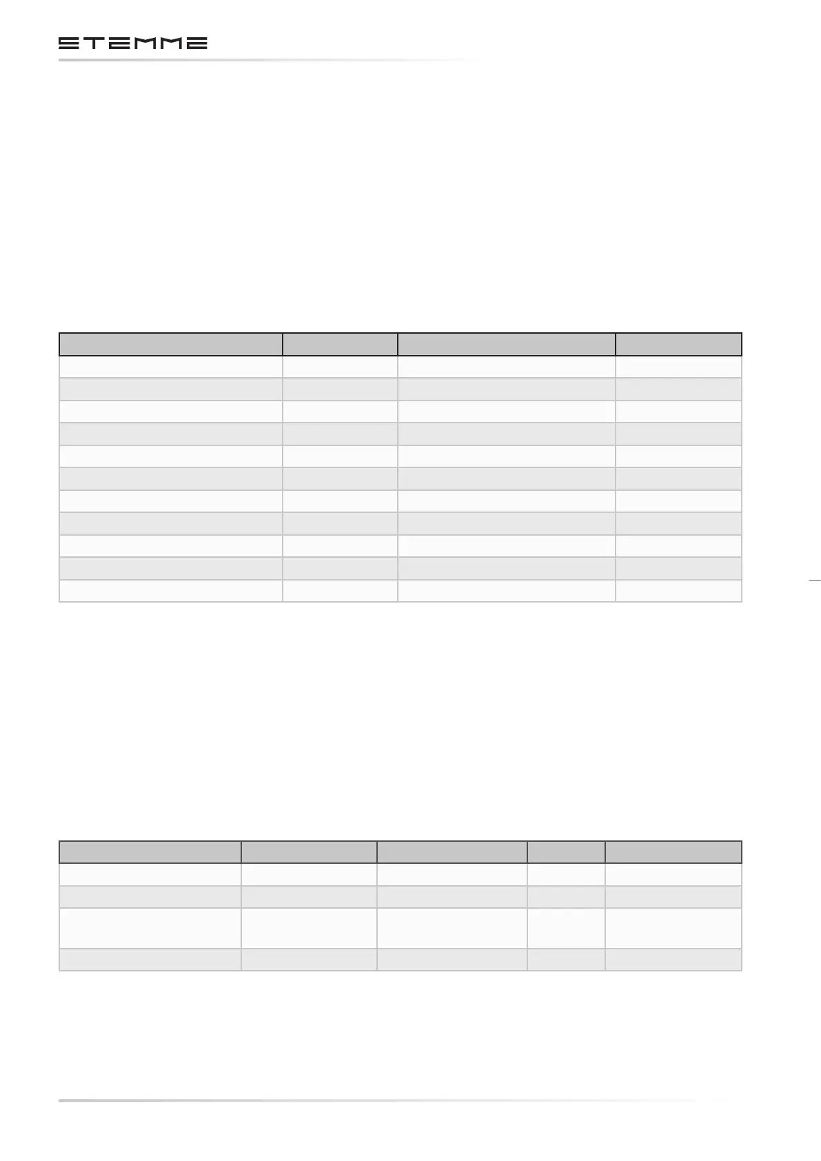
consumption of more than 3 A. Each switch is clearly labeled with its function.
Function STEMME p/n Electrical Load Rating
Master Switch 831.151 Relay Coil, < 1 A 3 A
Auxiliary Fuel Pump ON 831.151 MOSFET Gate, < 0.1 A 3 A
Engine System Back-Up 831.151 Relay Coil, < 1 A 3 A
TCU Emergency 831.151 Relay Coil, < 1 A 3 A
Transfer Pump Selector 831.507 Waste Gate Servo, < 2A 0.15 A
Landing Gear UP/DOWN 831.225 MOSFET Gate, < 0.1 A 20 A
Ignition-Starter-Key-Switch 831.107 Relay Coils, < 2 A
Position Light Switch 831.493 MOSFET Gate, < 0.1 A 3 A
ACL Switch 831.493 MOSFET Gate, < 0.1 A 3 A
Landing Light 831.493 MOSFET Gate, < 0.1 A 3 A
Propeller Pitch 831.151 MOSFET Gate, < 0.1 A 3 A
3.7.7.2 ELECTROMECHANICAL RELAYS
Power relays are used as master relays for the main system and the engine system, as starter relay
and as contactor for the optional ground power supply. The relays are typically ground-controlled,
the control switch is connected to the negative side of the relay coil. This improves the system
reliability.
Each relay is rated suciently for its electrical load.
Function STEMME p/n Rating Fuse Qualication
Main System Master 831.416 70 A 50 A
Engine System Master 831.416 70 A 50 A
Starter Relay 830.725 75 A cont. / 300 A
short time
80 A Part of certied
engine
Ground Power Relay 831.111 75 A 80 A