DOCUMENT NUMBER:
L500-912.820 ISSUE JUL 20, 2016
AMENDMENT: 00
DATE:
CHAPTERPAGE 350
MAINTENANCE MANUAL STEMME S12
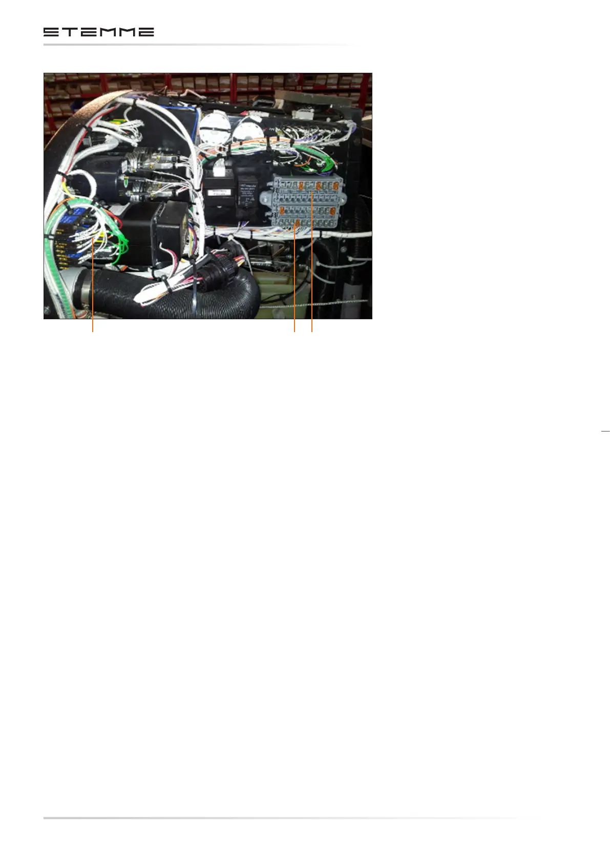
1. Circuit Breakers for Avionics
2. Engine Bus
3. Main Bus
Figure 3.7.c
Electrical Components Instrument Panel
3.7.12 ENGINE STARTING SYSTEM ATA 800000
3.7.12.1 DESCRIPTION
The electrical starter is connected via starter relay to the engine system battery. The starter re-
lay is controlled by the combined ignition-starter-key-switch located on the instrument panel.
The control circuit for the relay triggers an ignition retarding module which allows the foldable
propeller to unfold the blades completely before the engine res. This protects the blade folding
mechanism from damages caused by engine starting torque.
3.7.12.2 PARTS SPECIFICATION
Starter and starter relay are part of the engine, their specications can be found in the
ROTAX 914 Maintenance Manual.
3.7.12.3 OPERATION
The starter relay is triggered when the key switch is pushed to the “Start” position. The procedure
to start the engine is described in the S12 Aircraft Flight Manual.
1 2 3