DOCUMENT NUMBER:
L500-912.820 ISSUE JUL 20, 2016
AMENDMENT: 00
DATE:
CHAPTERPAGE 342
MAINTENANCE MANUAL STEMME S12
3.7.6 DC POWER DISTRIBUTION SYSTEM ATA 246000
The system is designed to distribute electrical energy from the source to the electrical loads. Be-
cause the engine of the S12 is located in mid-fuselage, there are long distances between voltage
sources and the loads.
Therefore, special attention is paid to subdivide the system into functional assemblies which in-
cludes sub-distributions with related protective devices.
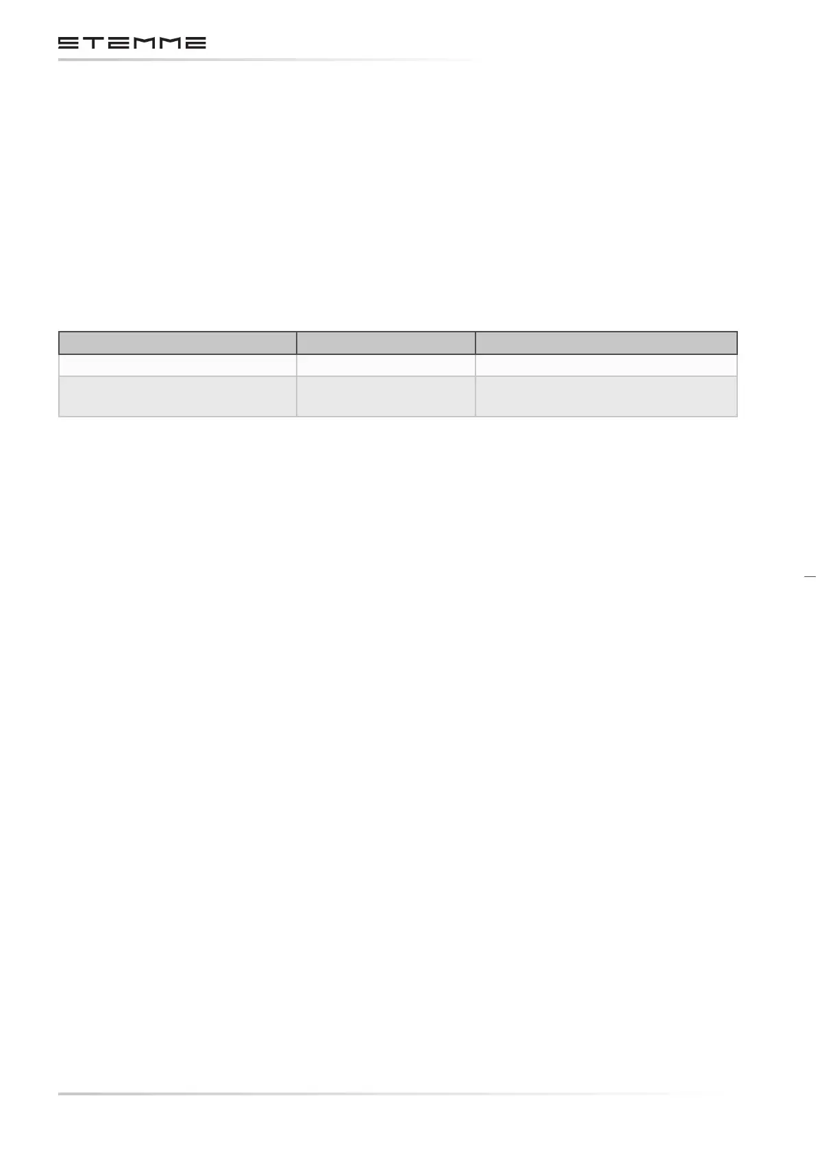
3.7.6.1 WIRE SPECIFICATIONS
Cross Section Specication
Battery and Starter Cables 16 mm² EN 50525-2-81
All other, unshielded and
shielded
AWG 24...8 MIL-22579/16 or
Raychem 44A
The cross section of each single wire is optimized individually.
The wires are bundled with spiral wrap to a wire harness. This harness is routed and xed along
the aircraft’s steel tube frame from the electrical distribution rack to the instrument panel. Inside
the cockpit, the wire bundle is routed along the tunnel between the seats.
Sucient distance to moving parts and heat sources is provided. Mechanical damage by tight
bending or chang is prevented.
3.7.6.2 DESIGN OF ELECTRICAL CONNECTIONS
Electrical connections are made by screw terminals, push-on contacts or multiple position
connectors.
Terminals and contact pins are generally crimped to the wires. Use of soldering techniques is
minimized.
Terminals and connector systems meet industrial standards.