Studer Innotec SA
next3
Technical user manual V1.3 © Studer-Innotec SA 121
8.8.2
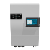
Device Information
On the nx-interface, the information screen for the device and its auxiliaries is shown below:
Explanation:
• Red point: mean the relay/entry is deactivated. For the relay, it means it is in the NC position.
• Green point: mean the relay/entry is activated. For the relay, it means it is in the NO position.
A list of all available information’s can be accessed with the + sign from this screen:
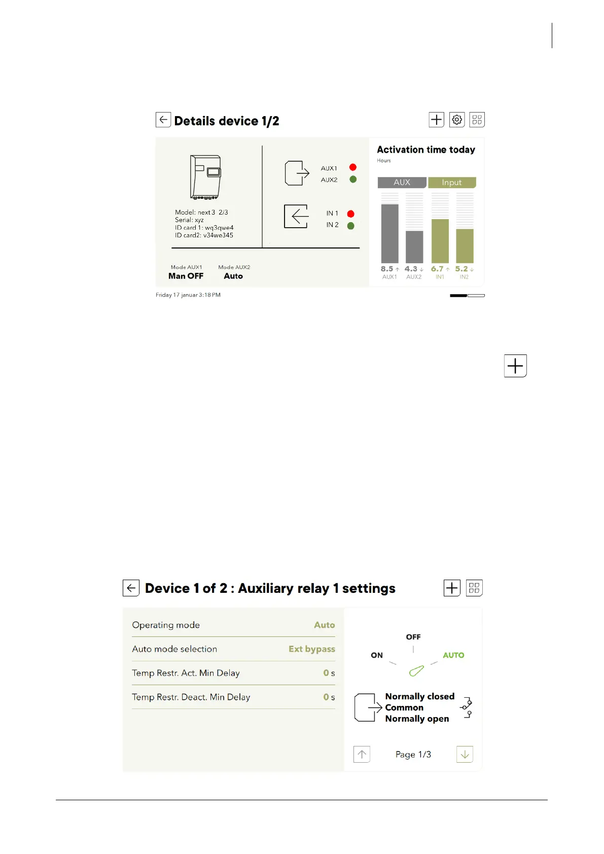
8.8.3
AUX-contacts settings
The auxiliary contacts can be programmed to open and close under various conditions.
For the end-user, the most common use of the contact is to start a generator, or to switch
on/off a load (up to 16A ac).
The programming is done mainly with a simplified menu (at level 3) proposing the choice
between Modes:
• Manual OFF: always deactivated, in position NO. This is also the unpowered state.
• Manual ON: always activated, in position NC
AUTO: some activation/deactivations conditions are used. This list of possibilities are exactly
the same as for the Flex load and will not be repeated below.
One setting is specific to AUX relays. It it is the Ext bypass for External bypass control.