Studer Innotec SA
next3
Technical user manual V1.3 © Studer-Innotec SA 43
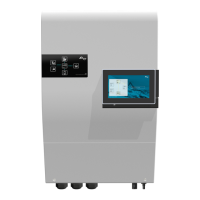
the PV+ is situated left and the PV- is situated right. Check carefully the indications written on the NX3
in case of doubt.
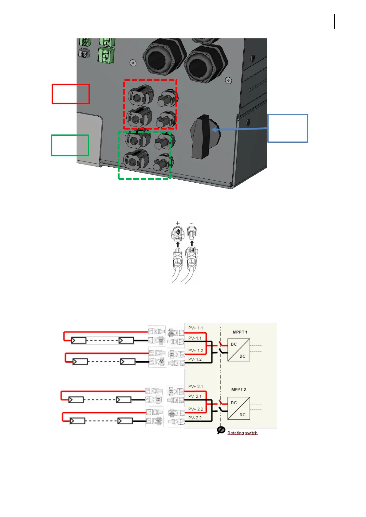
For one MPPT, if two strings are connected in parallel, they must be composed of the same types of
modules, and the same number of modules, to avoid voltage mismatch and production losses.
5.4.3
Earthing of PV
The MPPT topology is non-isolated for best efficiency, so the poles of the PV must not be grounded.
The electronics was designed to avoid fluctuating voltages on the PV poles. In operation, there is a