Studer Innotec SA
next3
Technical user manual V1.3 © Studer-Innotec SA 25
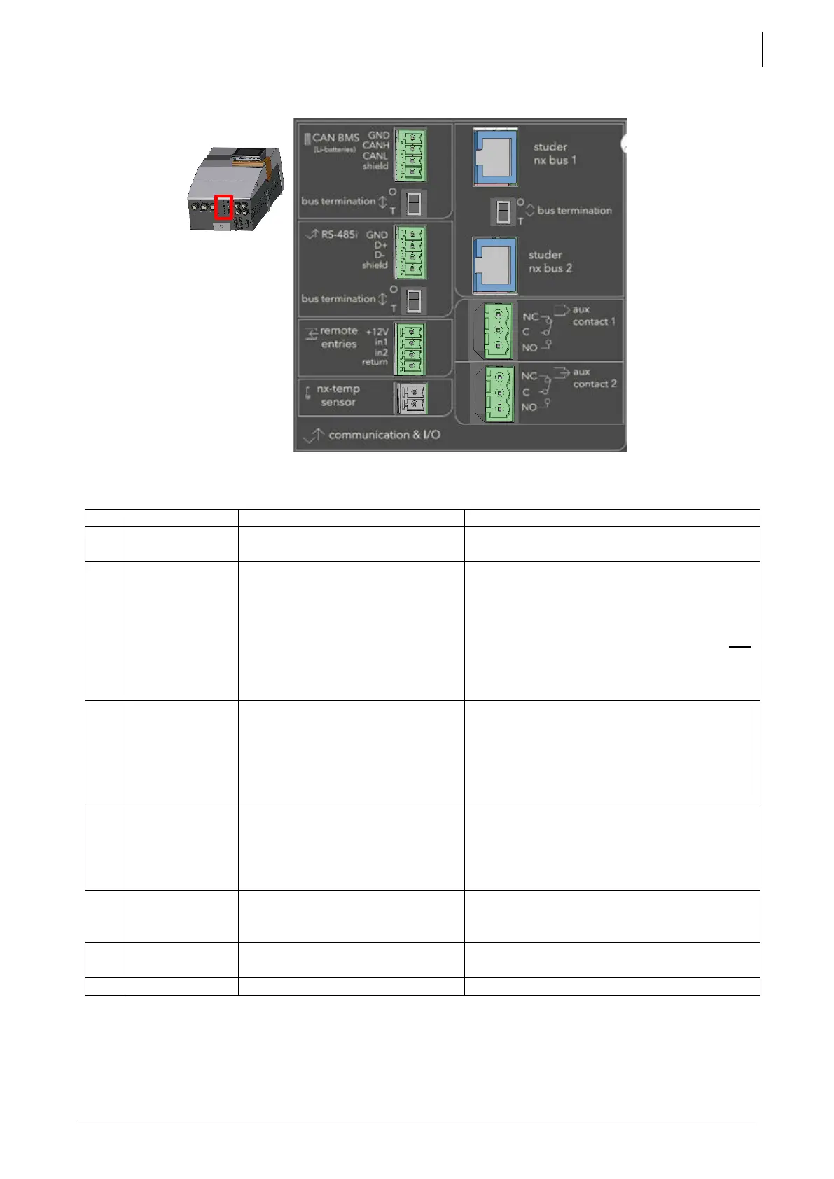
Communication and I/O connections:
See corresponding chapter for detailed wiring and protocol in use.
Connector for the battery
temperature sensor.
Only connect the original Studer nx-
tempSensor.
Two connectors for internal
communication between
studer next devices such as
the nx-interface or other next
units
Only nx-bus compatible device can be
connected. The connection of any other
device (LAN routers, can-to-can
interfaces, etc.) may damage the
device. See chapter 4.6. The nx-bus is not
compatible with other communication
bus from Studer (for example Xtender
bus).
Termination
switch
O / T
(Open /
Terminated)
Switch for terminating the
communication bus.
Set position (open) if the 2 connectors (3)
are occupied. Set position T if only one is
occupied.
The connectors at the two ends of the
communication bus daisy chain must be
terminated.
Programmable dry contacts.
16A/230V
Take care not to exceed the admissible
loads.
C: Common
NC: Normally Closed
NO: Normally Open
Isolated CAN bus for
communicating BMS of lithium
batteries
Two digital inputs to indicate
external changes to the unit.
See schematics in the “Wiring auxiliaries
I/O” chapter.
To come in future versions…