5
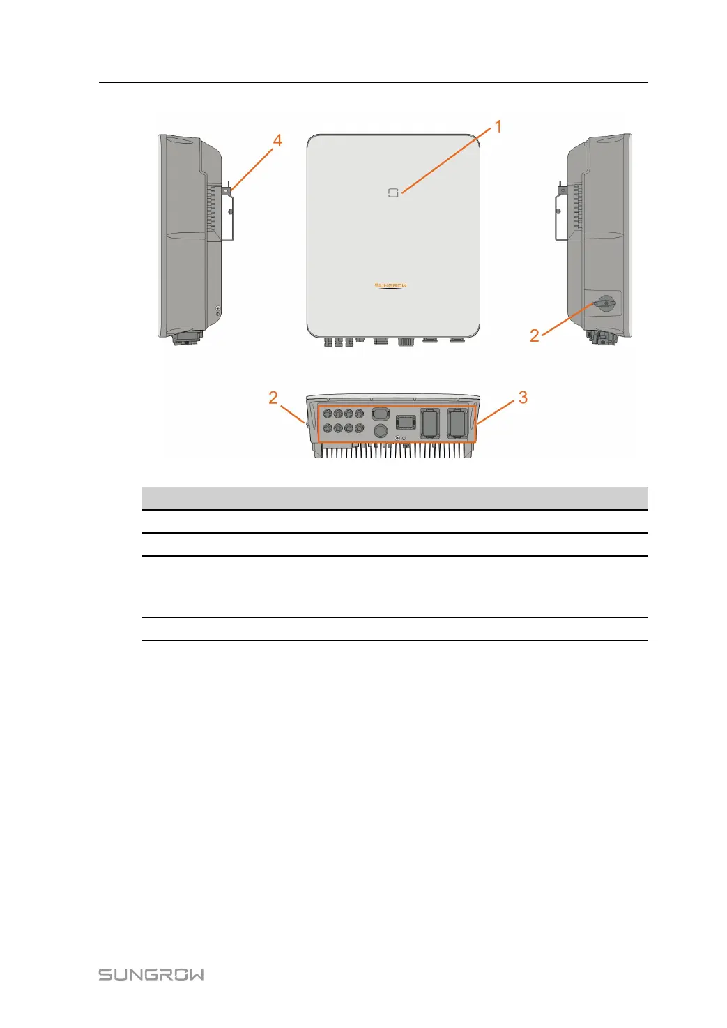
figure 2-1 Inverter Appearance
No. Name
Description
1
LED indicator panel Indicates the current working state of the inverter.
2 DC switch *
Used to safely disconnect the DC circuit.
3
Electrical connection
area
Includes DC terminals, AC terminals, battery terminals,
communication terminals and additional grounding
terminal.
4
Hanger Used to hang the inverter on the wall-mounting bracket.
* This function is only available for non-AU versions.
Dimensions
The following figure shows the dimensions of the inverter.
User Manual 2 Product Description