32
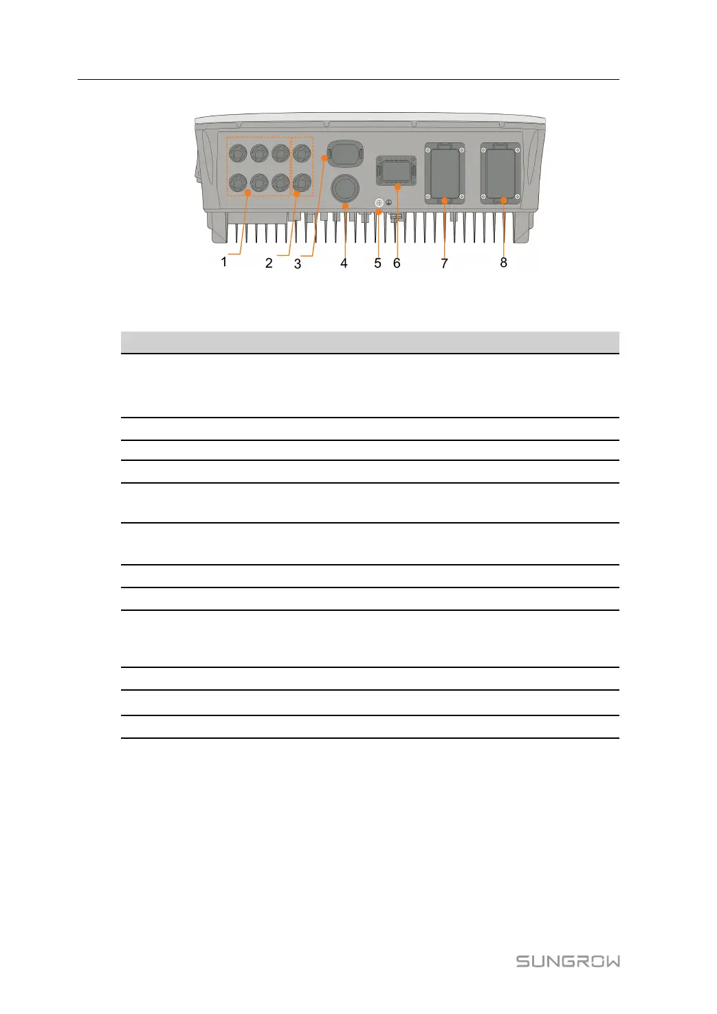
figure 6-1 Terminals at the Bottom of the Inverter
* The image shown here is for reference only. The actual product received may differ.
No. Name
Description
1 PV terminals
Positive and negative DC input connectors
Two or three pairs, depending on the inverter
model
2
Battery connection Connectors for the battery power cables
3 WLAN terminal Connector for the WiNet—S module
4 LAN terminal
Connector for the EMS, router, and data logger
5
Additional grounding
terminal
For reliable grounding
6 COM terminal
Connector for Smart Energy Meter, RS485, BMS/
CAN, DRM/DI and DO
7 BACK-UP terminal
AC terminal reserved for Backup loads
8 GRID terminal
AC terminal for connection to the utility grid
table 6-1 The label of COM terminal
Meter BMS/CAN DI/DRM DO
A2 B2 H L D1/5 D3/7 R NO
A1 B1
EN_H EN_G
D2/6 D4/8 C
COM
RS485 Enable
6 Electrical Connection User Manual