Website: www.sunsynk.com E-mail: sales@globaltech-china.com
25
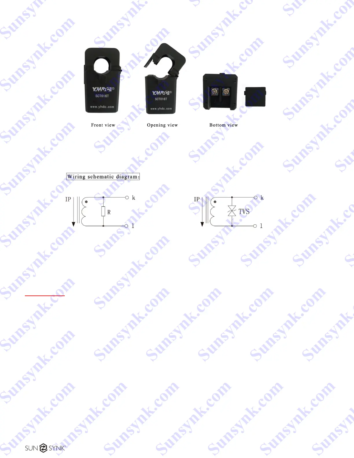
An example presented in Figure 20 and Figure 21 shows the wiring schematic diagram.
Figure 20 - 16mm aperture split core current transformer.
Figure 21 - Wiring schematic diagram.
IMPORTANT:
You need to be careful when using the CT coil. Please ensure that it is wired correctly.
If you want to export, you can, but the benefit of the CT coil is that the power generated during the day
can be consumed by the house appliances and/or, instead of being exported, it can also be stored in the
batteries for later use.
1) Fit the coil (sensor) around the live cable on the main fuse feeding the building and run the cable back
to the inverter. This cable can be extended up to an extra 10m using a similar cable.
2) Connect the other end of the CT coil into the inverter terminals marked as CT coil. It basically allows
the Grid Connection to work as a one-way street.
Built-in sampling resistance
Voltage Output Type
Voltage Output Type
TVS: Transient Voltage Suppressor
Current Output Type
Secondary will prevent short-circuit
Sunsynk.com Sunsynk.com Sunsynk.com Sunsynk.com
Sunsynk.com Sunsynk.com Sunsynk.com Sunsynk.com
Sunsynk.com Sunsynk.com Sunsynk.com Sunsynk.com
Sunsynk.com Sunsynk.com Sunsynk.com Sunsynk.com
Sunsynk.com Sunsynk.com Sunsynk.com
Sunsynk.com Sunsynk.com Sunsynk.com
Sunsynk.com Sunsynk.com
Sunsynk.com Sunsynk.com
Sunsynk.com
Sunsynk.com
Sunsynk.com Sunsynk.com Sunsynk.com Sunsynk.com
Sunsynk.com Sunsynk.com Sunsynk.com
Sunsynk.com Sunsynk.com Sunsynk.com
Sunsynk.com Sunsynk.com
Sunsynk.com Sunsynk.com
Sunsynk.com
Sunsynk.com