ELECTRICAL SYSTEM 6-5
B/Y
SWITCH
Measure the engine stop switch and emergency switch for conti-
nuity using a tester. If any abnormality is found, replace the switch
assembly with a new one.
ENGINE STOP SWITCH
WIRE COLOR
B/R: Black with Red tracer B/Y: Black with Yellow tracer
B/W: Black with White tracer
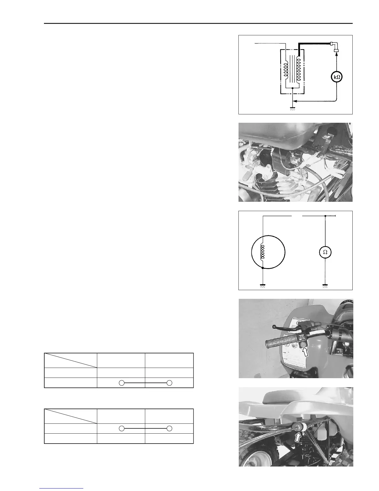
GENERATOR COIL RESISTANCE
• Remove the seat. (!5-2)
• Remove the frame cover. (!5-2)
• Disconnect the generator lead wire.
Measure the resistance between the Black/Yellow lead wire and
ground. If the resistance is not within the specified value, replace
the generator with a new one.
& Generator coil resistance:
: 100 – 160
ΩΩ
ΩΩ
Ω (Black/Yellow – Black/White)
IGNITION COIL RESISTANCE
Measure the ignition coil resistance in the secondary winding. If
the winding is in sound condition, the resistance should be close
to the specified value.
& Ignition coil resistance
Secondary: 13 – 20 k
ΩΩ
ΩΩ
Ω (Spark plug cap – Ground)
EMERGENCY SWITCH
Position
Color
B/R B/W
RUN
OFF
Position
Color
B/Y B/W
PULL
FREE