PSX-5300 Installation PSX Module Installation and Cable Connection
DOC-001-11001 (Rev. 006)
31 DNX Quick Install & Setup Guide
PSX Module Installation and Cable Connection
1. Install the Protection Switch Controller module.
2. Connect the DB9 male-to-male Serial Interface Cable to the DB9 connector on the PSX
Controller module.
3. Connect the opposite end to the DB9 connector located System Manager Rear Interface
Module, marked Protect Swt (SMC II) or PSX (SMCII A).
4. Install the primary and redundant interface modules.
Note: The Primary and Redundant Interface modules have a one-to-one correspondence
with the DNX-11 Interface modules; see Table 2.
For details on connecting Narrowband and Broadband modules, refer to “Narrowband Cable
Connections” on page 32 or “Broadband Cable Connections” on page 32.
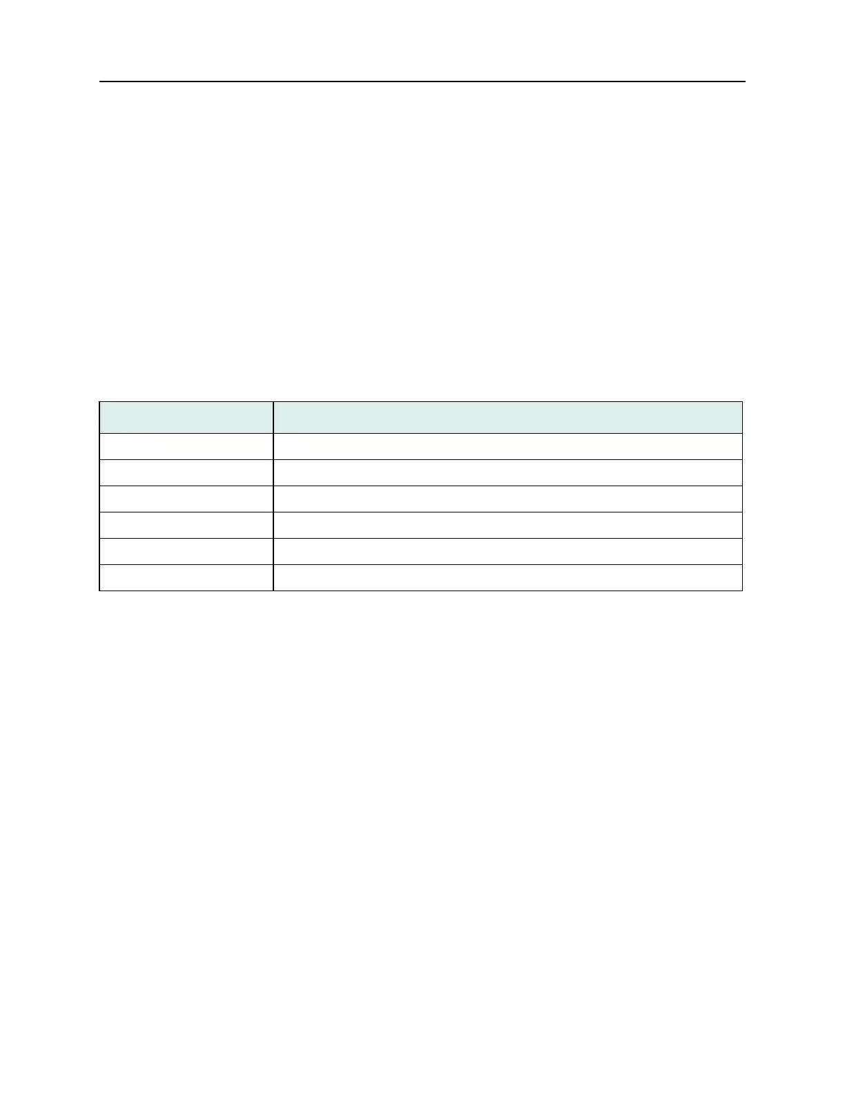
Table 2: One-to-one Correspondence.
Slot Module
Slot 1: Narrowband (e.g., Octal T1/E1) Redundant Card
Slots 2-11: Narrowband (e.g., Octal T1/E1) Primary Card
Slot 11: Broadband Group 1 (e.g., HDS3) Redundant Card
Slots 8-10: Broadband Group 1 (e.g., HDS3) Primary Card
Slot 7: Broadband Group 2 (e.g., STS1) Redundant Card
Slots 1-6: Broadband Group 2 (e.g., STS1) Primary Card